
Zero center of mass archery cam

a technology of center of mass and archery cam, applied in the field of archery bows, can solve the problems of affecting the archer's aim, causing the rest of the system to gyrate, vibration/shock movement, and disrupt the archer's aim, so as to reduce or eliminate the effect of gyration or kick

Active Publication Date: 2005-12-08
BEAR ARCHERY
View PDF11 Cites 14 Cited by
  • Summary
  • Abstract
  • Description
  • Claims
  • Application Information

AI Technical Summary

Benefits of technology

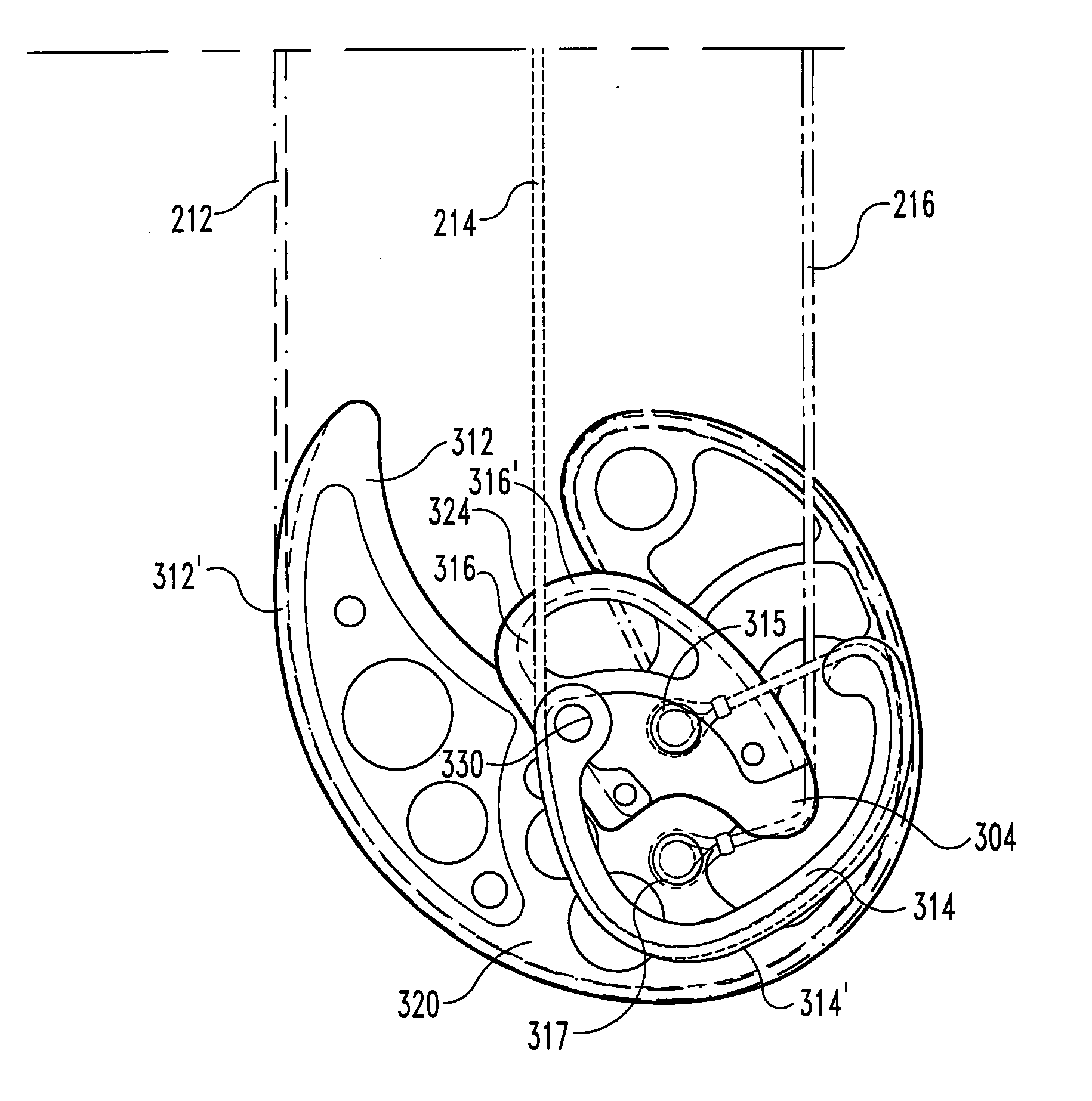
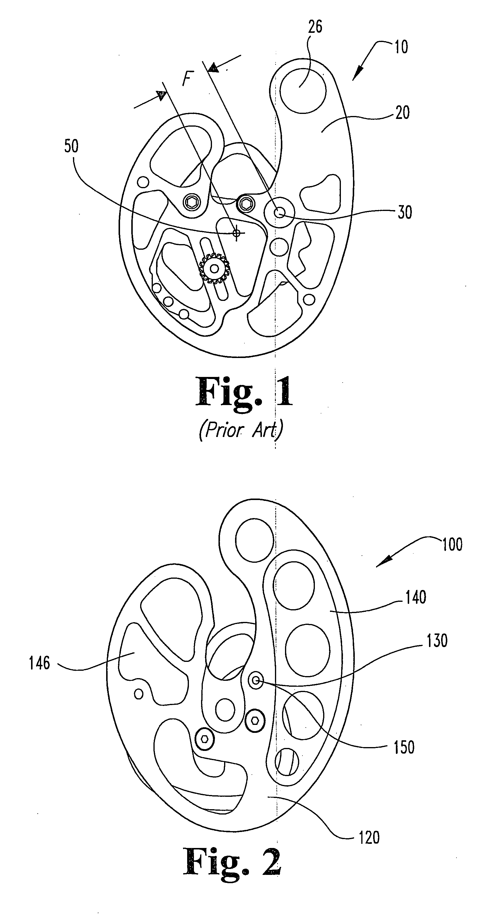
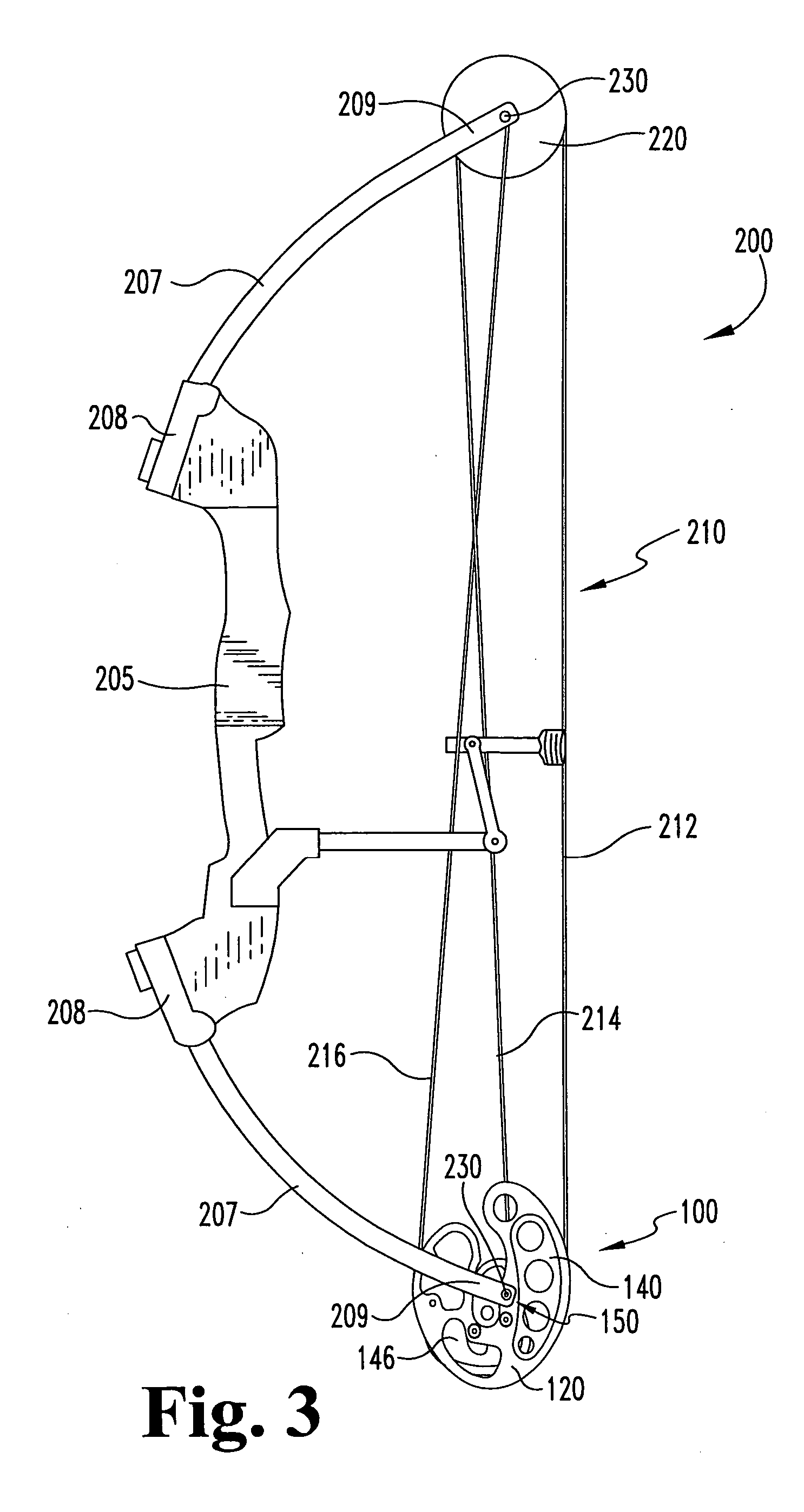
[0008] In certain embodiments of the present invention, by arranging, placing or reducing the weight / mass at one or more locations on the cam (FIG. 2), the effective center of mass can be zeroed to the centerline of the axle to reduce or eliminate this gyration or kick. In a preferred embodiment, a “zeroed” cam with a center of mass co-axial with the axle location will spin freely as a concentric wheel does on a central axis. The even distribution of mass around the axle eliminates the traditional kick or gyration upon bowstring release typically created by an eccentrically located axle hole.

Problems solved by technology

When rotated about an axle, the inertia of the off-center mass produces a kick which causes the rest of the system to gyrate.
This causes a kick or vibration / shock movement which is imparted to the bow and archer when the bow is shot.
This kick can disrupt the archer's aim or the archer absorbs this energy as opposed to the energy being transferred to the arrow or the arrow's flight.
Nevertheless, even when the perimeter weighted cam and vertical limb technology were used together, the bow still typically had a kick.

Method used


Image

  • Zero center of mass archery cam
  • Zero center of mass archery cam
  • Zero center of mass archery cam

Examples


example

[0075] To test and illustrate the kick or vibration / shock reduction of an embodiment of the present invention, a bow mounted with a cam according to the present invention was tested against a bow mounted with a perimeter weighted cam (PWC). The test bow used was a Jennings model CK3.5 bow equipped with a perimeter weighted cam and then equipped with a “zero center of mass” cam according to a preferred embodiment of the present invention. The test data is shown in graphical form in FIG. 14.

[0076] The specifications for the Jennings model CK3.5 bow with a perimeter weighted cam were as follows:

Test ResultsFriction (ft-lbs)6.86Fwd Curve (ft-lbs)75.99Rev curve (ft-lbs)69.13% Let-Off (effective)83.47Min Force (lbs)11.00True Draw (in)27.11A-A (in)35.25Brace (in)8.20Power Stroke (in)18.91Peak Force (lbs)66.59AMO Draw Length (in)28.86Holding Wt (lbs)11.00

[0077] The specifications for the Jennings model CK3.5 bow with a zero center of mass cam were as follows:

Test ResultsFriction (ft-lb...


PUM


Abstract

One preferred embodiment of the present invention provides a cam having an axle location for mounting the cam to an archery bow, where the center of mass of the cam is substantially coaxial with the axle location. Preferable the cam has an eccentric geometric rotation profile with regard to a rotation axis, typically an irregular geometry with a non-centered axle location, or a circular profile with an axle location offset from the center of the circular profile. The mass of the cam is balanced to have an effectively equal mass distribution around the axle location. In an alternate preferred embodiment, the cam has a balanced center of mass aligned with the axle location in an X-Y orientation, and may also have a balanced center of mass through the thickness of the cam in an X-Z or Y-Z orientation.

Description

FIELD OF THE INVENTION [0001] The present invention relates to archery bows, and in preferred embodiments provides a cam for a compound archery bow, a compound bow and cam, and a method of making and arranging a cam. BACKGROUND OF THE INVENTION [0002] The present invention deals primarily with compound archery bows, generally including a bow frame and a cable system on the frame mounted to at least two rotational elements such as wheels. Early compound bow wheels or cams were basically a round wheel with the axle hole located off center to produce let-off as the bow is pulled to full draw. These eccentrically mounted wheels have a mass center off-set from the axle hole. When rotated about an axle, the inertia of the off-center mass produces a kick which causes the rest of the system to gyrate. This causes a kick or vibration / shock movement which is imparted to the bow and archer when the bow is shot. This kick can disrupt the archer's aim or the archer absorbs this energy as opposed...

Claims


Application Information

Patent Timeline
IPC IPC(8): F41B5/10F41B5/18
CPCF41B5/10Y10S124/90F41B5/105
Inventor GALLOPS, HENRY M. JR.
Owner BEAR ARCHERY
Learn More