
Press forming method

a press and forming technology, applied in forging presses, forging/pressing/hammering apparatuses, shape safety devices, etc., can solve the problems of slide plate inclination relative to a fixed plate, imbalance in load moment acting on drive sources, slide plate inclination, etc., and achieve high forming speed

Inactive Publication Date: 2005-11-24
HODEN SEIMITSU KAKO
View PDF5 Cites 8 Cited by
  • Summary
  • Abstract
  • Description
  • Claims
  • Application Information

AI Technical Summary

Benefits of technology

[0024] if the difference between the reference delay and the displacement delay of one of the other drive sources is more than the predetermined value, preparing a speed increment (hereinafter referred to as “compensation increment”) for the one of the other drive sources, corresponding to the difference between the reference delay and the displacement delay so as to eliminate the difference between the reference delay and the displacement delay for the one of the other drive sources to add the compensation increment to the descending speed of the trial forming for the one of the other drive sources,

Problems solved by technology

Using a large slide plate, the single drive source disposed in a center of the slide plate cannot uniformly press the slide plate.
The variations of the magnitudes and the working positions of the loads cause imbalance on load working on the slide plate.
Then, imbalance in load moments acting to the drive sources is caused.
So, since a drive source subjected to a large load is more delayed in proceeding than a drive source subjected to a small load, a slide plate is caused to incline relatively to a fixed plate.
The inclination of the slide plate causes a die to incline and often to be injured.
When the inclination of the slide plate is small, the die is not injured but may reduce accuracy in press-forming a work-piece.
However, when a slide plate inclination is prevented during press-forming by the feed-back control, a cycle of press forming takes a long time.
If a cycle of press-forming takes a long time, there is a problem that a production of a large number of work-pieces takes an extremely long time.

Method used


Image

  • Press forming method
  • Press forming method
  • Press forming method

Examples


Embodiment Construction

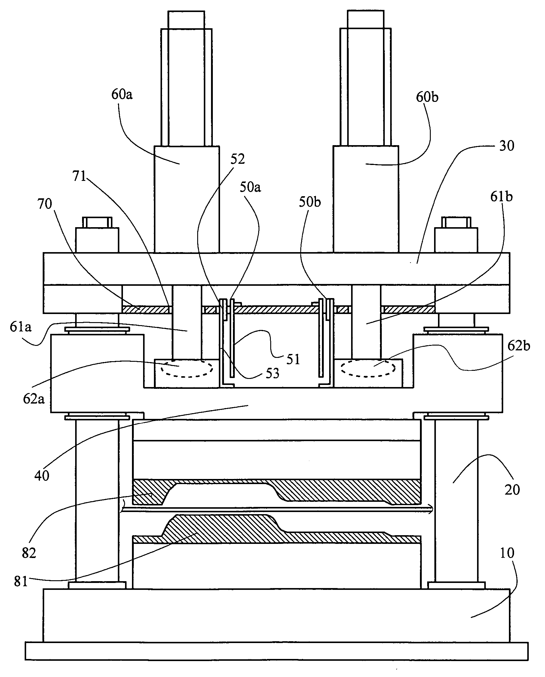
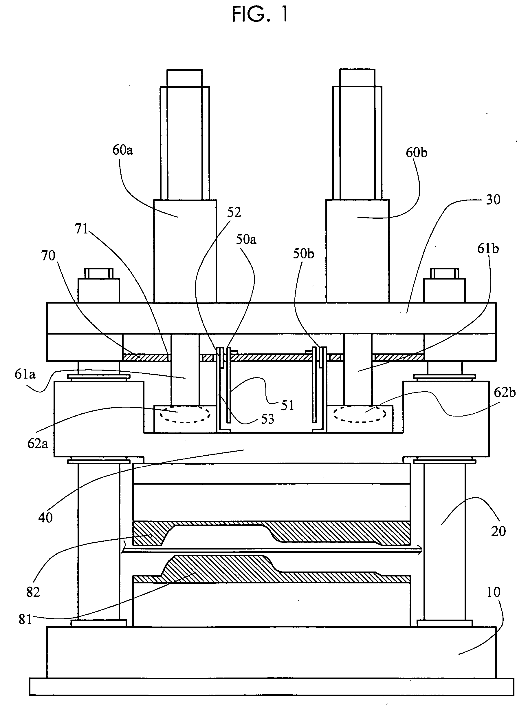
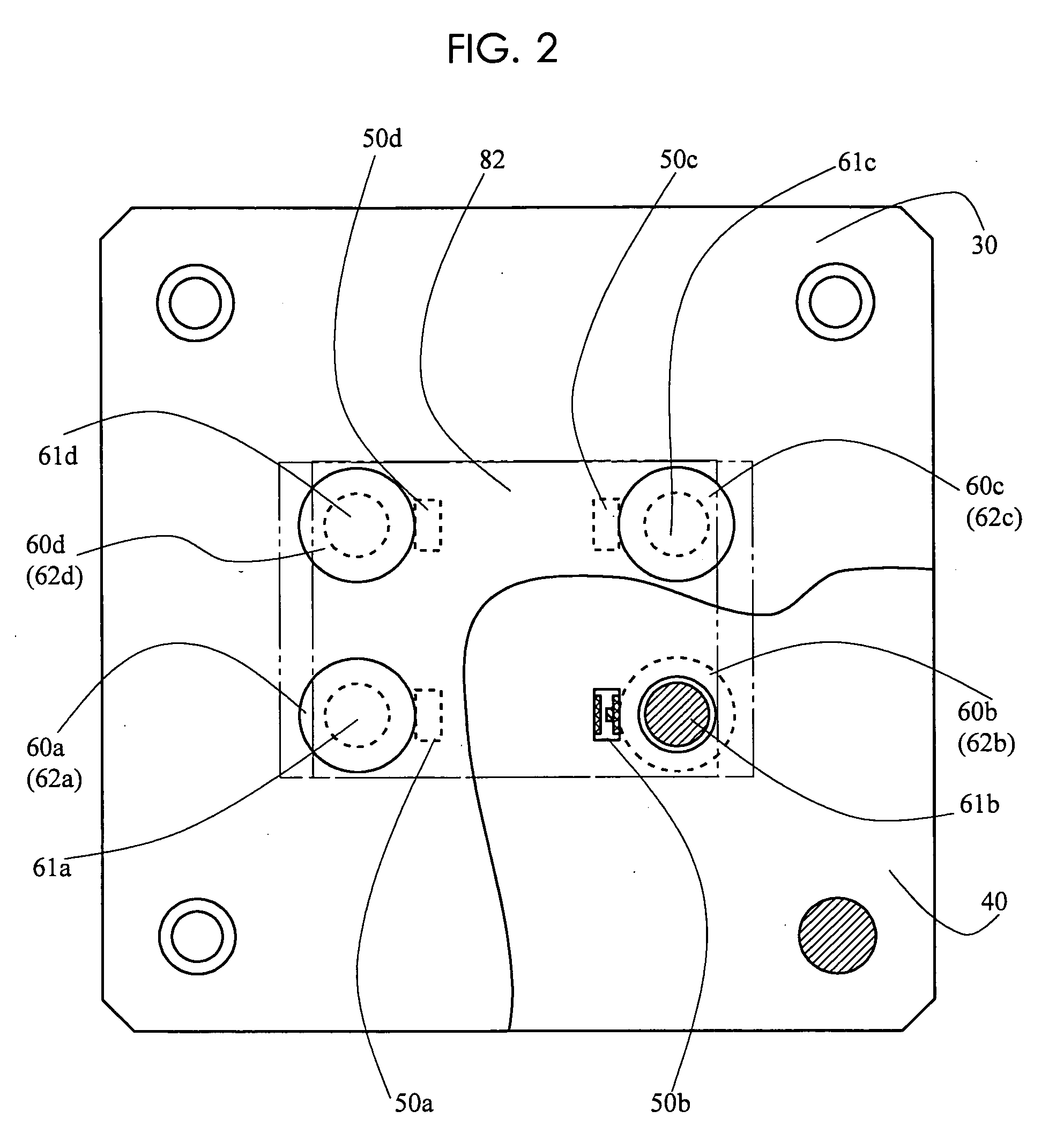
[0040] Referring to FIGS. 1 and 2 first, an example of a press machine which can be used for the invention will be described. FIG. 1 is a front view of the press machine, and FIG. 2 is a plan view of the press machine. In FIG. 2, the press machine is shown with an upper support plate partially removed. The press machine has a lower support base 10 fixed on a floor surface, and has an upper support plate 30 by supporting columns 20 made upright on the lower support base. A slide plate 40 capable of reciprocating along the supporting columns 20 is provided between the lower support base 10 and the upper support plate 30, and a forming space exists between the slide plate and the lower support base. In this forming space, a fixed die (lower die) 81 for press-forming is mounted on the lower support base, while a movable die (upper die) 82 corresponding to the fixed die is mounted on an undersurface of the slide plate, and for example, a plate to be formed is placed between these dies an...


PUM

PropertyMeasurementUnit
displacementsaaaaaaaaaa
speedsaaaaaaaaaa
speedaaaaaaaaaa

Abstract

A press forming method is disclosed, wherein press forming can be effected at high speed while maintaining the horizontal state of a slide plate in press-forming work by a press machine. A press machine is used in which the slide plate is pressed by a plurality of servo-motor drive sources. In trial forming, the slide plate is sufficiently slowly moved to measure the delay of each drive source. According to the magnitude of the delay of each drive source or according to the difference between the trial forming speed and the production forming speed, the respective speeds of the drive sources are corrected, and trial forming is repeated on the basis of the corrected speed to derive conditions that enable press forming at high forming speed suitable for mass production while maintaining the horizontal state of the slide plate to the extent of ensuring sufficient product accuracy.

Description

TECHNICAL FIELD [0001] The invention relates to a press forming method in which a slide plate is maintained to be horizontal during press forming, using a press machine that drives a slide plate or a pressing plate by a plurality of drive sources, e.g. servo-motors, to press-form. BACKGROUND ART [0002] A press machine for press-forming a work-piece has a structure which has a fixed plate, a slide plate opposite to the fixed plate, a fixed die disposed on the fixed plate and a movable die disposed on the slide plate facing the fixed plate to open and close the movable die against the fixed die by moving the slide plate relatively to the fixed plate. In a small press machine, there is a single drive source provided in a center of a slide plate. Using a large slide plate, the single drive source disposed in a center of the slide plate cannot uniformly press the slide plate. Therefore, using a plurality of drive sources to cause a uniform pressing force on a slide plate, each of the plu...

Claims


Application Information

Patent Timeline
Patent Type & Authority Applications(United States)
IPC IPC(8): B30B1/18B30B15/20B30B15/14B30B15/24
CPCB30B1/18B30B15/24B30B15/14B30B15/20
Inventor FUTAMURA, SHOJIUNNO, KEIZO
Owner HODEN SEIMITSU KAKO
Learn More