
Battery lock

a battery lock and battery technology, applied in the field of battery locks, can solve the problems of difficult or at least time-consuming, large and heavy batteries for aircrafts, even light aircraft,

Inactive Publication Date: 2005-11-10
D&K GRP
View PDF11 Cites 51 Cited by
  • Summary
  • Abstract
  • Description
  • Claims
  • Application Information

AI Technical Summary

Benefits of technology

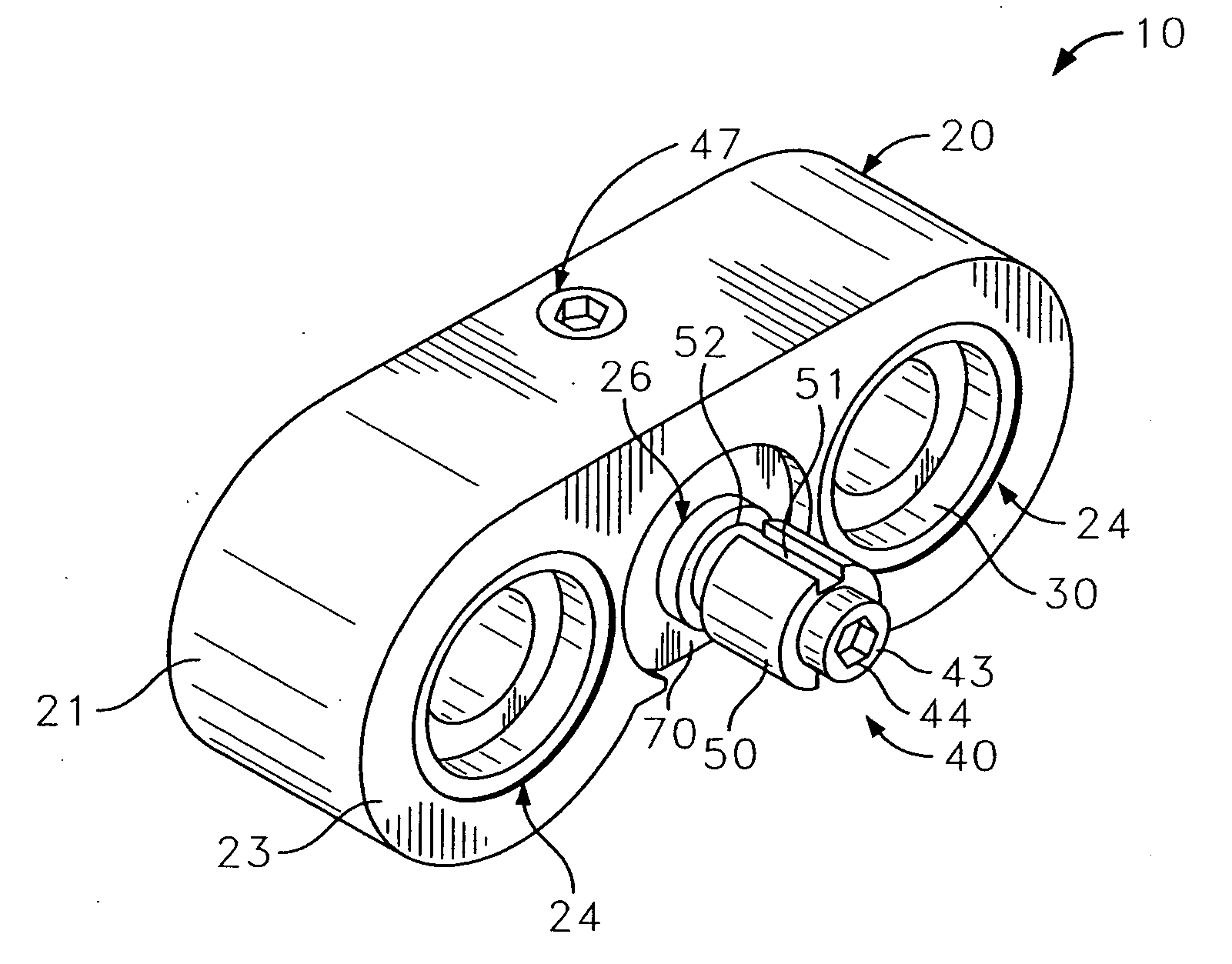
[0006] The present invention basically locks the aircraft's battery. It prevents someone without an appropriate key from attaching the electrical umbilical line to the battery. The battery lock of the present invention works with batteries having a receptacle with an inner side wall and a back wall for receiving a connector (e.g., socket) for connecting the battery to the aircraft. The battery's receptacle includes a pair of terminals projecting outwardly from the back wall of the receptacle and the receptacle has at least one transverse protuberance projecting outwardly from an inner side wall of the receptacle.
[0007] According to a first aspect of the present invention, the lock includes a block with an exterior side surface generally conforming to a portion of the inner side wall of the receptacle. This permits the block to be seated within the receptacle. It further prevents external access to one or more of the battery's terminals. A locking mechanism cooperates with the block and is rotatable between at least a first position and a second position. In the first position the locking mechanism can pass by the protuberance, permitting the block to be seated in and removed from the receptacle. In the second position the locking mechanism is prevented from passing by the protuberance, prohibiting the block from being removed from the receptacle. A key assembly communicates with the locking mechanism to rotate the locking mechanism between the just described first and second positions when a mating key is inserted into the assembly.

Problems solved by technology

The batteries for aircrafts, even light planes, can be quite large and heavy, weighing upwards of 100 lbs. apiece.
This can be difficult, or at least time consuming, if the plane compartment within the aircraft is also locked.
These just noted regulations only hamper theft; they do not prevent theft.

Method used


Image

  • Battery lock
  • Battery lock
  • Battery lock

Examples


Embodiment Construction

[0020] While this invention is susceptible of embodiments in many different forms, there is shown in the drawings and will herein be described in detail, preferred embodiments of the invention with the understanding the present disclosure is to be considered as an exemplification of the principles of the invention and is not intended to limit the broad aspect of the invention to the embodiments illustrated.

The Battery 100

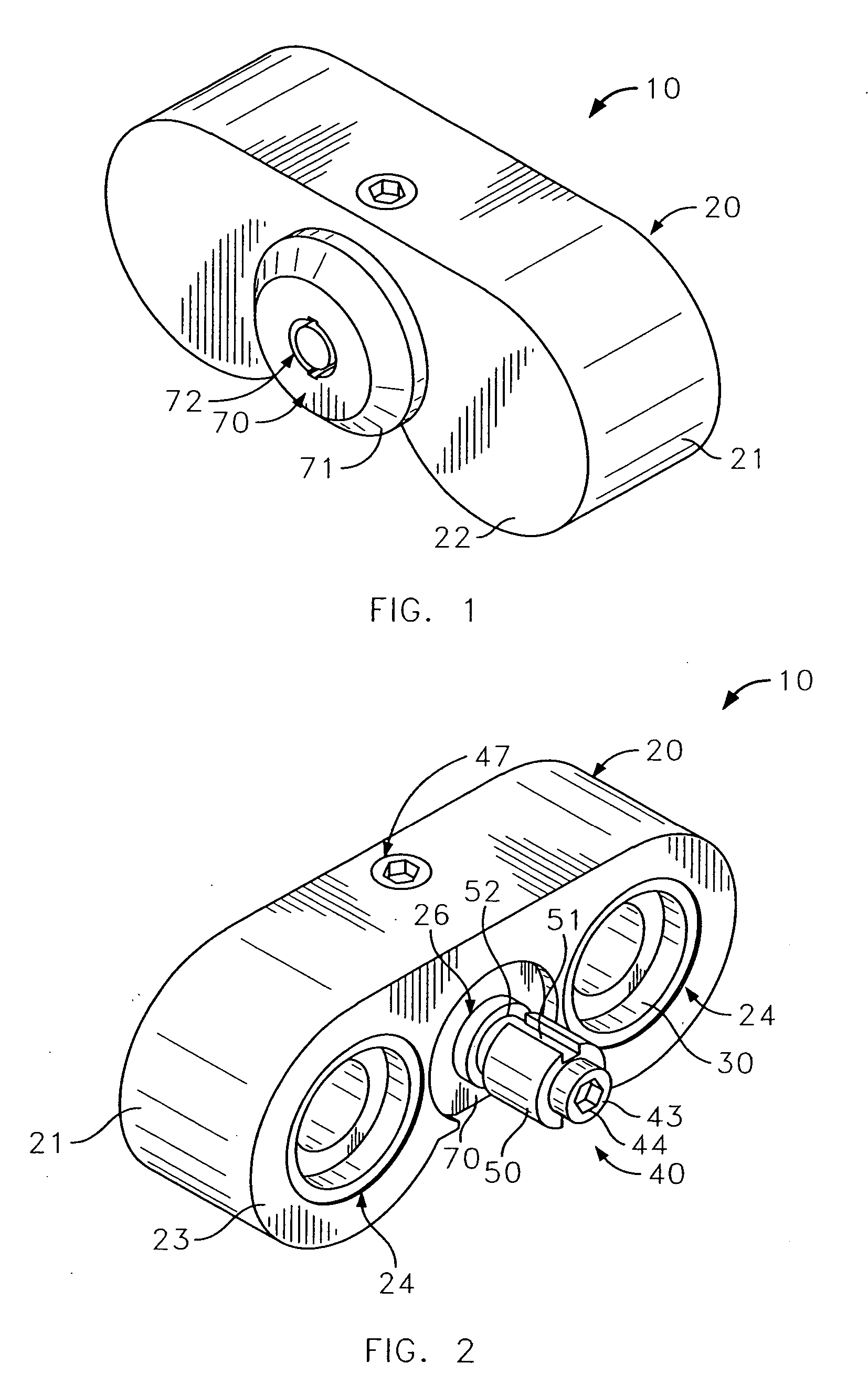
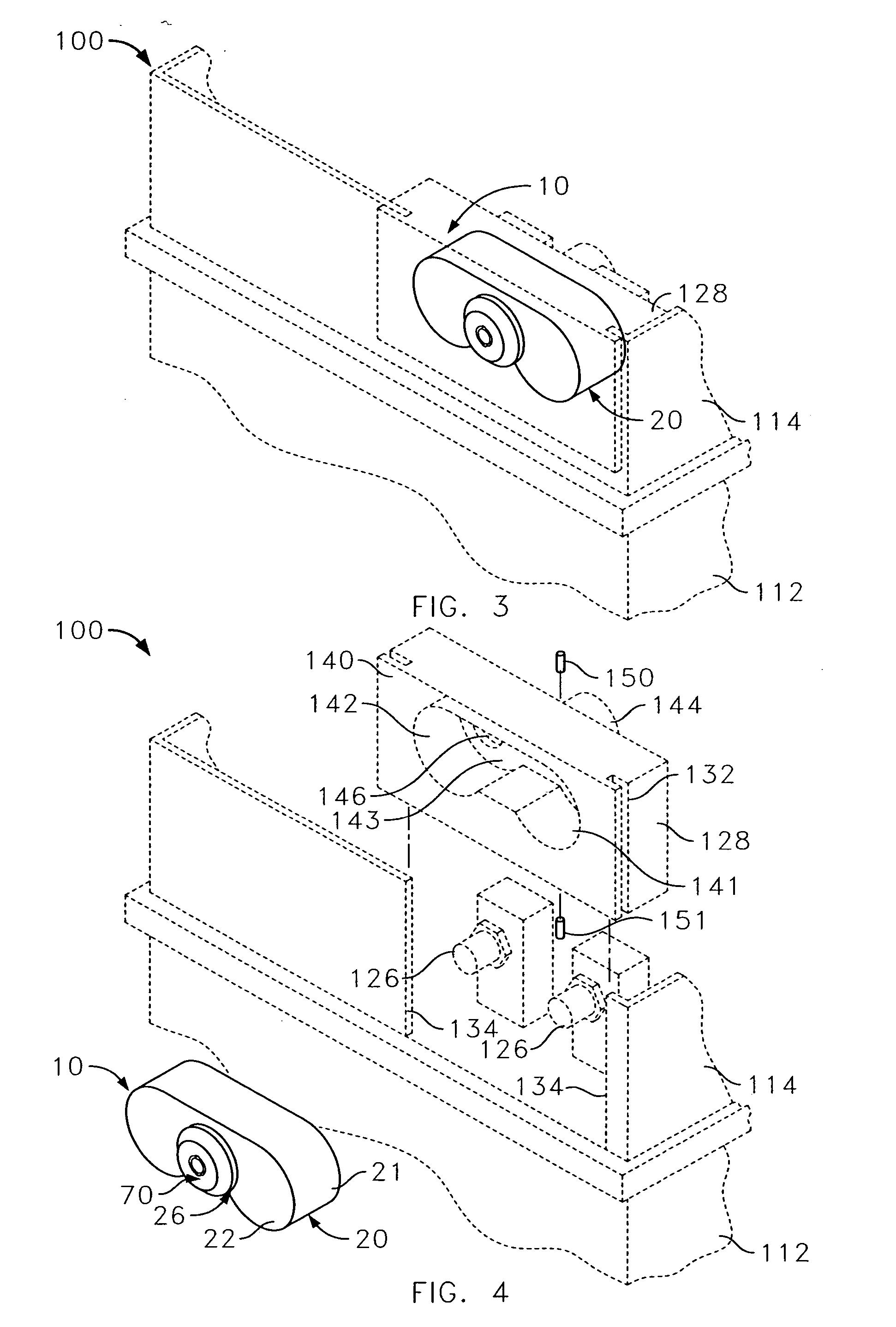
[0021] The battery lock of the present invention is generally designated by reference number 10. As shown in FIGS. 1 and 2, the lock 10 includes three principle components, a block 20, a locking mechanism 40 and a key assembly 70. The lock 10 shown in the present embodiment is designed to mate with an airplane battery, generally designated by reference number 100 (FIGS. 3-6).

[0022] The airplane battery 100 shown in the figures is typical of batteries used in small aircraft and is a lead-acid type of battery. For example, this type of battery is disclosed in U.S. ...


PUM


Abstract

A battery lock (10) includes a block (20), a locking mechanism (40) and a key assembly (70). Rotating the proper key will rotate the key mechanism (40) and a sleeve (50) disposed around a shaft (41), permitting the block (20) to pass by a pair of protuberances (150,151) within a cavity (144) to remove the lock (10) from a receptacle (141) or to lock the locking mechanism (40) behind the protuberances (150,151). In this manner, one can insert the battery lock (10) into the battery's (100) receptacle (141), secure the lock (10) in place and remove it.

Description

CROSS-REFERENCE TO RELATED APPLICATIONS [0001] This application is a continuation of U.S. Ser. No. 10 / 729,819 filed Dec. 5, 2003, which is incorporated herein by reference.TECHNICAL FIELD [0002] The present invention generally relates to locking mechanisms, and more particularly, to a lock used for batteries used in aircrafts. BACKGROUND OF THE INVENTION [0003] The batteries for aircrafts, even light planes, can be quite large and heavy, weighing upwards of 100 lbs. apiece. One such lead-acid aircraft battery is disclosed in U.S. Pat. Nos. 4,337,301 and 4,419,815. This battery has an external receptacle and two externally projecting terminal posts therein. External electrical connections to the terminal posts are normally made by a socket containing female channels and electrical contacts therein for cooperating with the terminal posts. The socket is secured within the receptacle and electrical contact is made with the posts. The socket is connected to an electrical umbilical line s...

Claims


Application Information

Patent Timeline
Patent Type & Authority Applications(United States)
IPC IPC(8): E05B65/00H01MH01M2/10H01M2/30H01M2/34H01R13/625
CPCH01M2/344H01M50/598Y02E60/10Y10T70/5009
Inventor SINGER, KARLSEEDORF, CHAD
Owner D&K GRP
Learn More