Passive optical network with protection mechanism and its method of relocation

Inactive Publication Date: 2005-11-10
IND TECH RES INST
View PDF6 Cites 13 Cited by
  • Summary
  • Abstract
  • Description
  • Claims
  • Application Information

AI Technical Summary

Benefits of technology

[0010] In view of the foregoing, an objective of the invention is to provide a passive optical network with a protection mechanism and its method of relocation. It has the ability of relocation of ONU, thereby increasing the usefulness and lowering the maintenance cost of the passive optical network. Moreover, the bandwidth usage rate can be increased.
[0012] Therefore, once the optical network, or even the first couplers, the second couplers, or the OLT is out of order, the invention can immediately switch to another normal route without waiting. It thus has a protection mechanism to guarantee the privilege of the business or home users. On the other hand, through the control of the controller and the arrangement of double routing, the invention avoids manual relocation that forbids network usage. The network bandwidth can be optimized by dynamical relocation too.

Problems solved by technology

When these shared devices or routes are out of order, all users on the passive optical network 10 will not be able to use the network.
This will result in great loss for the business or home users.
The circuit cannot be dynamically modified.
The users cannot use the network during the relocation, again resulting in user's loss.
In this case, the bandwidth usage rate is generally low for most of the time.
However, they still do not have the ability to dynamically adjust the OLT of the ONU.
However, a primary drawback is in the high cost of the optical exchanger.
Moreover, it cannot solve the problem of the breakdown of the ONU transmission ports and cannot achieve the ability of dynamically adjust the OLT of a single ONU.

Method used


Image

  • Passive optical network with protection mechanism and its method of relocation
  • Passive optical network with protection mechanism and its method of relocation
  • Passive optical network with protection mechanism and its method of relocation

Examples


Embodiment Construction

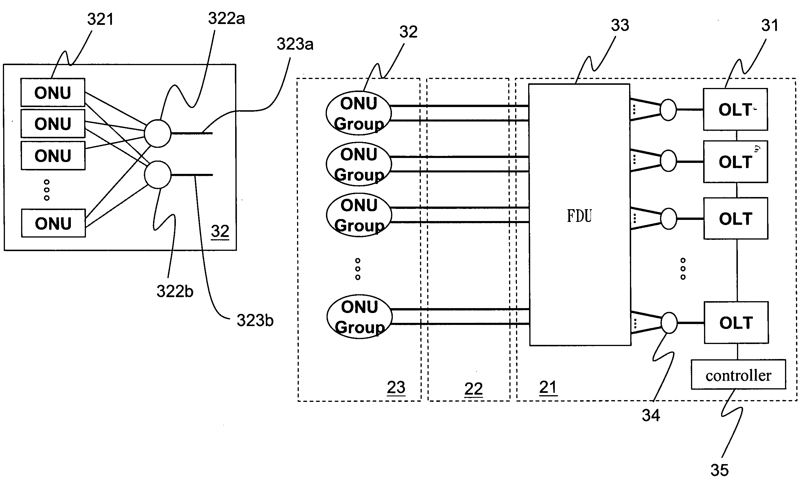
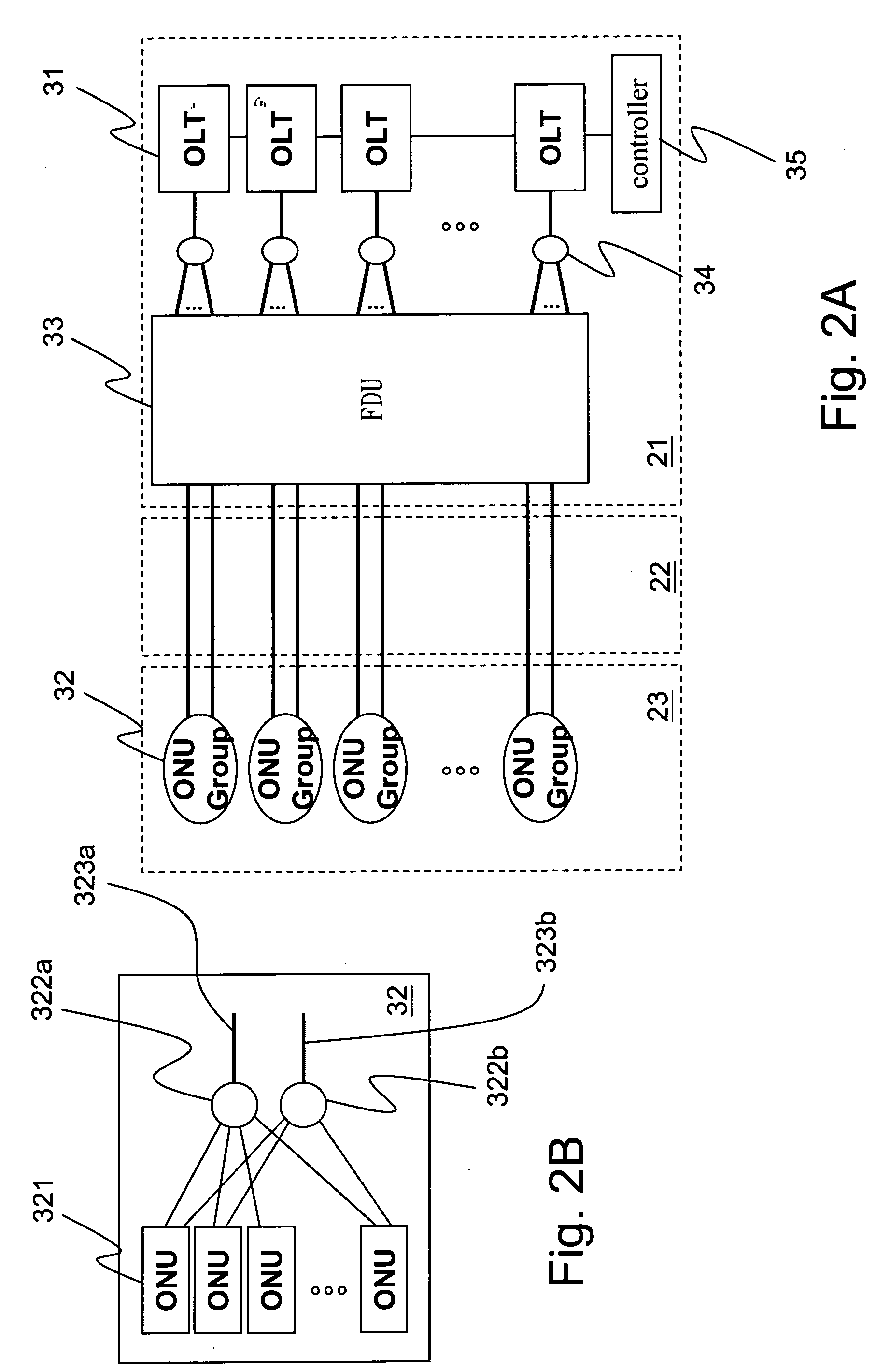
[0020] The disclosed passive optical network with a protection mechanism is shown in FIGS. 2A and 2B. It contains several OLT 31s and several ONU groups 32. The OLT 31 is connected to a controller 35 and controlled by the controller 35. It is connected out by a first coupler 34. Each ONU group 32 contains several ONUs 321 and connects out via two fibers 323a, 323b. The two fibers 323a, 323b of each ONU group 32 are connected to the first couplers 34 of different OLTs 31.

[0021] The ONU group 32 is located on the user end 23, connecting to the optical network 22 via the two fibers 323a, 323b and then to the central office end 21. In order for each ONU group 32 to connect to the first couplers 34 of different OLTs 31, the central office end 21 is designed with a fiber distribution unit (FDU) 33 to manage the fiber connections. The structure of the ONU group 32 is shown in FIG. 2B. Each ONU 321 is connected to the two second couplers 322a, 322b through two transmission ports, respectiv...


PUM


Abstract

A passive optical network with a protection mechanism and its method of relocation are provided. A plurality of optical network units is defined in several optical network unit groups. Each optical network unit connects to two couplers. The two couplers connect respectively to two different optical line terminals, which are controlled by a controller. Thus, when the optical lines run out or are overloaded, the controller relocates the optical network units dynamically.

Description

BACKGROUND OF THE INVENTION [0001] 1. Field of Invention [0002] The invention relates to a passive optical network and, in particular, to a passive optical network with a protection mechanism and its method of dynamical relocation. [0003] 2. Related Art [0004] Fiber to the premises is the future trend of network development. In particular, the passive optical network has the advantages of low costs in construction, maintenance, and management. Thus, it is a major possible implementation method. The structure of the Passive Optical Network is shown in FIG. 1. A set of passive optical network 10 is comprised of an optical line terminal (OLT) 11, a coupler 12, and several optical network units (ONU) 13. The OLT 11, which is on the central office end 17, is connected via a fiber 14 to the coupler 12 near the user end 18. The coupler 12 is then connected via fibers 15 to various optical network units 13. The optical distribution network between the central office end 17 and the user end ...

Claims


Application Information

Patent Timeline
IPC IPC(8): H04J14/00H04Q11/00
CPCH04Q11/0067H04Q2011/009H04Q2011/0081
Inventor LIAW, YI-CHINGLAI, JIM Z. C.CHOU, YUN-LUNGDUANMU, JIA-JAYCHANG, YAO-YAUN
Owner IND TECH RES INST
Why Eureka
Try Eureka