Vibration absorber system for an optical recording/reproducing apparatus

a technology of optical recording/recording apparatus and absorber, which is applied in the direction of recording information storage, record carrier contruction details, instruments, etc., can solve the problems of generating excessive vibration and noise, limited effectiveness of solutions, and rarely used, so as to reduce or eliminate imbalance of traverse modules, the effect of simple vibration absorber

Inactive Publication Date: 2005-11-10
HON HAI PRECISION IND CO LTD
View PDF8 Cites 2 Cited by
  • Summary
  • Abstract
  • Description
  • Claims
  • Application Information

AI Technical Summary

Benefits of technology

[0009] Accordingly, an object of the present invention is to provide a simple vibration absorber system for an optical recording / reproducing apparatus which effectively eliminates internal vibration.
[0010] Another object of the present invention is to provide a vibration absorber system for an optical recording / reproducing apparatus which can reduce or eliminate imbalance of a traverse module.
[0011] In order to achieve the objects set out above, a vibration absorber system for an optical recording / reproducing apparatus of the present invention is attached to one side of a chassis of a traverse module of the optical recording / reproducing apparatus. The vibration absorber system comprises a vibration absorber for soaking up vibration generated in the optical recording / reproducing apparatus, and at least two elastic dampers for elastically attaching the vibration absorber to the traverse module. Therefore, internal vibration is soaked up by the vibration absorber system. Further, the vibration absorber system may be attached to a lighter side of the chassis. Thus, imbalance of the traverse module is reduced or eliminated by the vibration absorber system.

Problems solved by technology

However, this solution is only effective when the spindle motor is rotating at high speed.
This is liable to generate excessive vibration and noise.
However, this solution has limited effectiveness and is seldom used.
However, the vibration absorber 3 is unduly complicated and costly to manufacture and assemble.
Therefore, the base 2 is liable to tilt because of imbalance.

Method used


Image

  • Vibration absorber system for an optical recording/reproducing apparatus
  • Vibration absorber system for an optical recording/reproducing apparatus
  • Vibration absorber system for an optical recording/reproducing apparatus

Examples


Embodiment Construction

[0017] Reference will now be made to the drawing figures to describe the preferred embodiment of the present invention in detail.

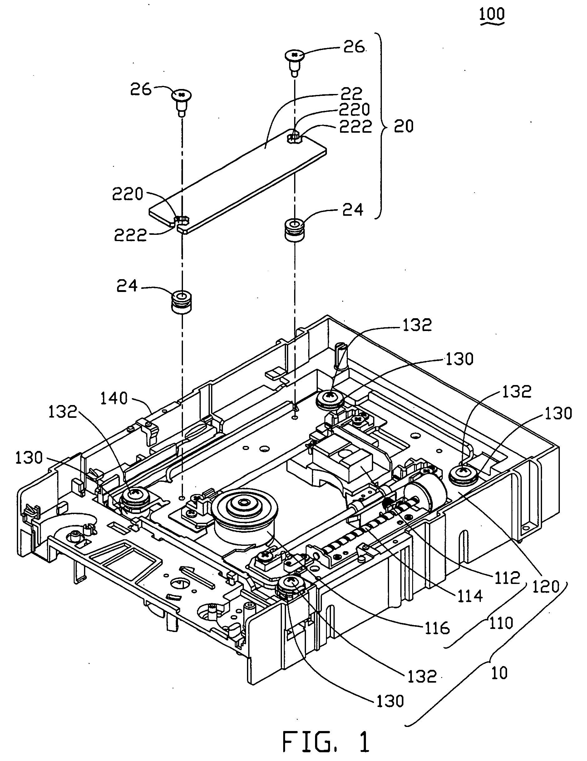
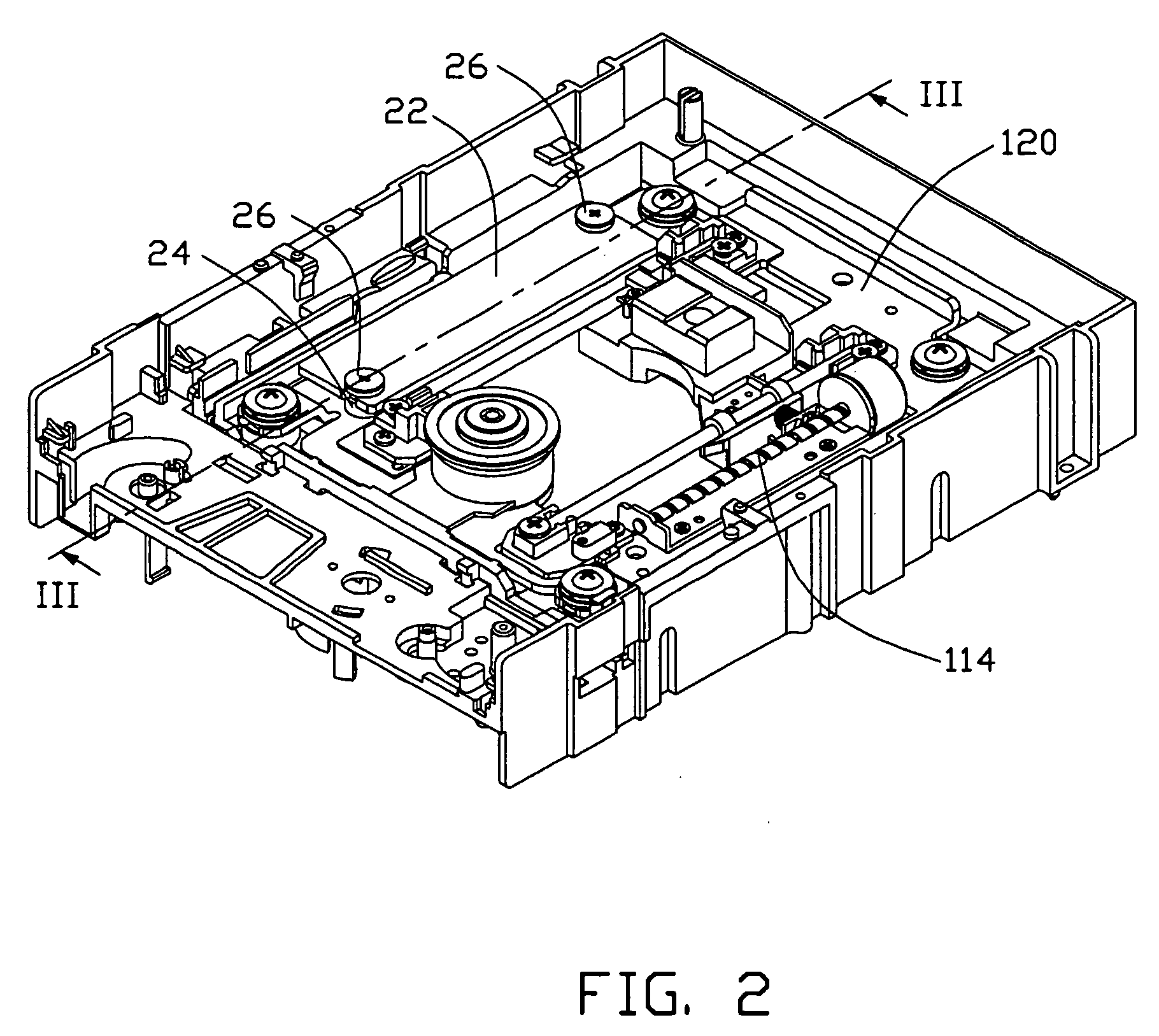
[0018] As shown in FIGS. 1 and 2, a traverse module 10 is mounted on a frame 140 via four elastic isolators 130 and four corresponding screws 132. The traverse module 10 comprises a driving unit 110 fixed on a rectangular chassis 120. The driving unit 110 comprises a pickup head 112 for recording / reproducing information to / from a disc, a feeding mechanism 114 for driving the pickup head 112, and a spindle motor 116 for rotating the disc. The pickup head 112 is slidable within a rectangular opening of the chassis 120, and is guided by a pair of parallel guiding rods (not labeled). The spindle motor 116 is mounted on a middle portion of a front end of the chassis 120. The feeding mechanism 114 is mounted on a long lateral side portion of the chassis 120.

[0019] A vibration absorber module 20 is arranged on an opposite long lateral side portion of the chassi...


PUM

PropertyMeasurementUnit
natural frequencyaaaaaaaaaa
vibratory frequencyaaaaaaaaaa
speedaaaaaaaaaa

Abstract

A vibration absorber system is attached to one side of a chassis of a traverse module of an optical recording / reproducing apparatus. The vibration absorber system includes a vibration absorber for soaking up vibration generated in the optical recording / reproducing apparatus, and at least two elastic dampers for elastically attaching the vibration absorber to the traverse module. Thus, internal vibration is soaked up by the vibration absorber system. Further, the vibration absorber system may be attached to a lighter side of the chassis. Thus, imbalance of the traverse module is reduced or eliminated by the vibration absorber system.

Description

BACKGROUND OF THE INVENTION [0001] 1. Field of the Invention [0002] The present invention generally relates to a vibration absorber system for an optical recording / reproducing apparatus, and more particularly to a vibration absorber system for an optical recording / reproducing apparatus which can effectively dampen vibration in the optical recording / reproducing apparatus and reduce or eliminate imbalance of a traverse module of the optical recording / reproducing apparatus. [0003] 2. Description of the Prior Art [0004] Recently, the speed of optical recording / reproducing apparatuses such as CD-Players and DVD-Players has been much improved, with speeds of 24x, 48x and even 52x being attained. A key reason for achieving much higher operation speeds has been the ability to limit the vibration generated by a rotating spindle motor or a feeding pickup unit of the optical recording / reproducing apparatus. A few major solutions are popular regarding vibration damping systems of conventional o...

Claims


Application Information

Patent Timeline
Patent Type & Authority Applications(United States)
IPC IPC(8): G11B7/00G11B33/02G11B33/08
CPCG11B33/08G11B33/022
Inventor WANG, CHUN-CHIEHTSAI, HUNG CHIEH
Owner HON HAI PRECISION IND CO LTD
Why Eureka
Try Eureka