Lading tie anchor link with enhanced banding contact surface

a technology of contact surface and anchor link, which is applied in the direction of load securing, transportation items, transportation and packaging, etc., can solve the problems of banding radius of anchor assembly, banding to fail, repetitive back and forth bending, etc., to reduce the risk of band breakage, reduce the “creasing” of metal banding, and enhance the configuration of the banding portion

Active Publication Date: 2005-11-10
IRECO INC
View PDF41 Cites 2 Cited by
  • Summary
  • Abstract
  • Description
  • Claims
  • Application Information

AI Technical Summary

Benefits of technology

[0018] In accordance with the present invention, an anchor assembly reduces the risk of band breakage at large tensile forces by providing a link with a large load bearing surface having an enhanced banding portion configuration which decreases “creasing” of metal banding that is anchored by the assembly and decreases bending stress transmitted to the steel band at the anchor location during rail transport, even over long distances and with lading loads having a relatively high center of gravity.

Problems solved by technology

One problem associated with prior art anchor assemblies which we now have determined to be important is that, when the steel bands are subjected to such large tensile forces, especially when combined with forces that result from even slight shifting of lading weight during the rocking movement of rail transport, there is the possibility that metal fatigue will cause the bands to fail.
The movement of rail transport can cause repetitive back and forth bending at locations where the banding engages a corner or tight radius.
We have determined that the banding radius of anchor assemblies as illustrated in FIGS. 1-4 is inadequate, especially when used to secure top-heavy or uneven loads, such as a load of steel pipes, the steel band can become creased along the curved corners of the banding portion, which creases are subjected to dynamic bending forces over time and subsequently break.
This is especially problematic when the cargo must be transported a great distance.
The steel band can withstand only a certain stress level and will deform and fail once that level is exceeded.
It is thought that the critical stress level decreases due to the combination of creasing, dynamic bending forces, and metal fatigue associated with prior art anchor assemblies.
The anchor assemblies of FIGS. 5 and 6 are relatively expensive because they require several components (i.e. a cylinder, a bolt, and a nut) to achieve their goal.

Method used


Image

  • Lading tie anchor link with enhanced banding contact surface
  • Lading tie anchor link with enhanced banding contact surface
  • Lading tie anchor link with enhanced banding contact surface

Examples


example

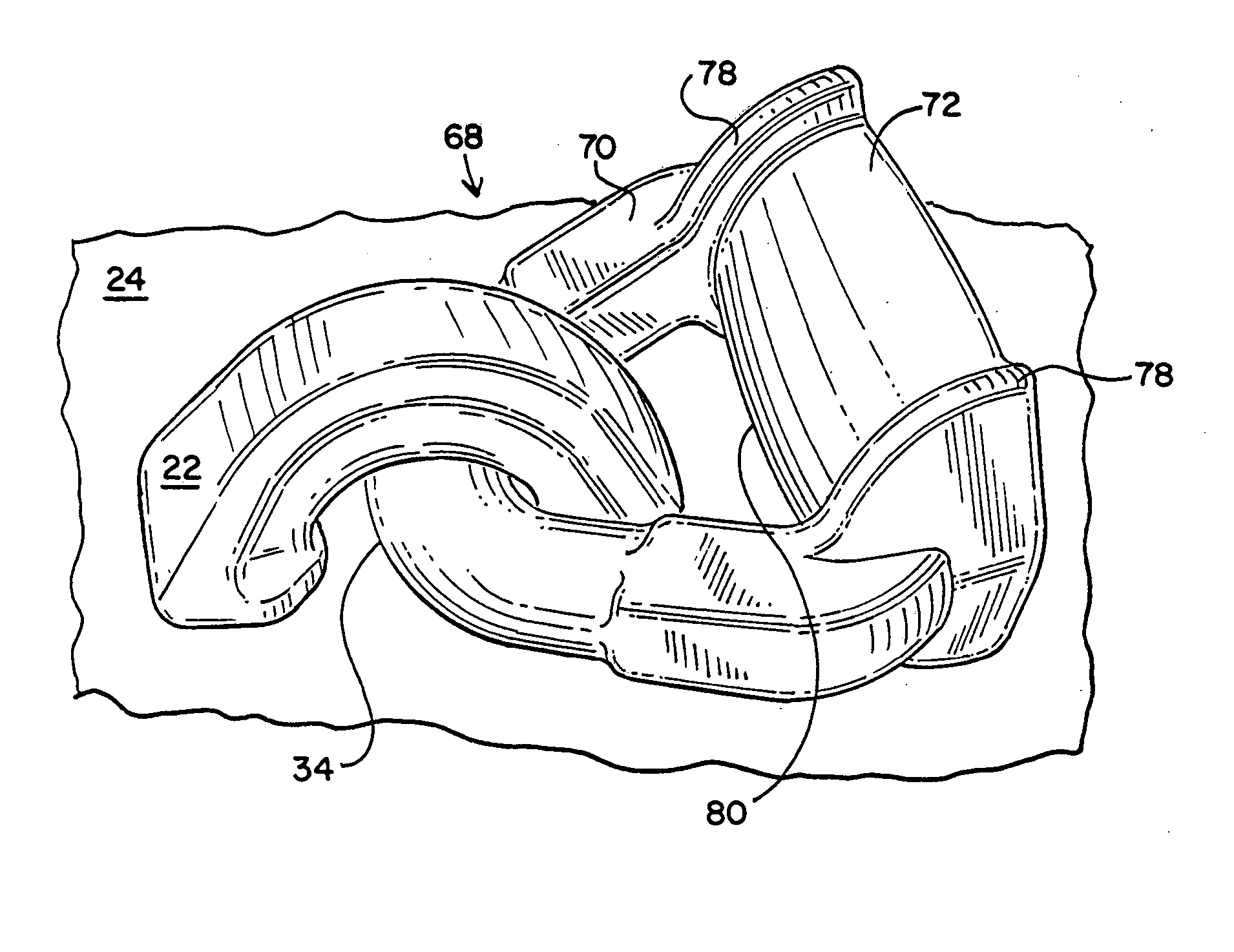
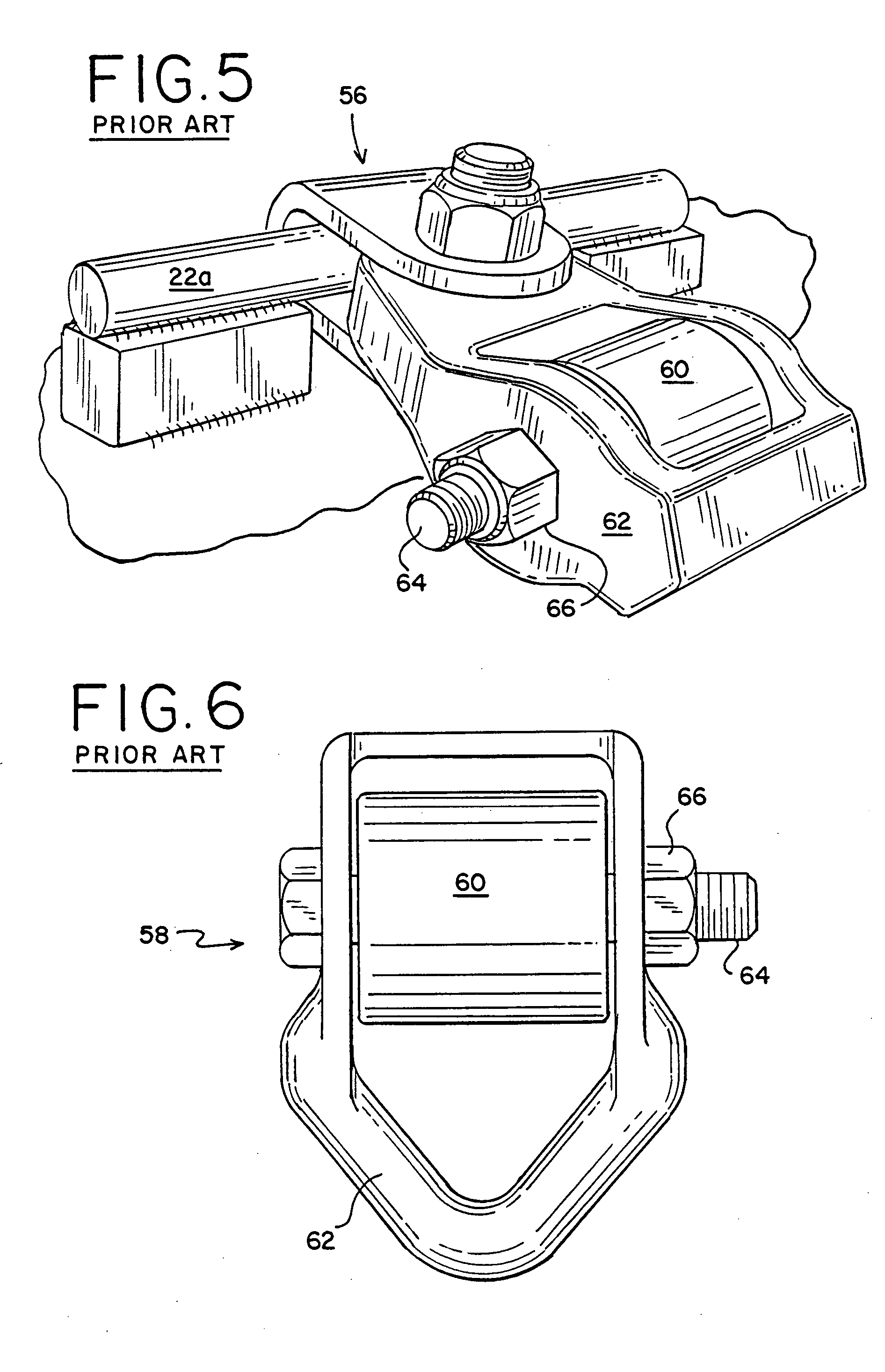
[0048] In a long-distance road test of about 1,000 miles along a commercial rail route, a link according to the present invention was compared to the prior art link of FIGS. 1-4 and the alternate retainer 22a which can be seen in FIG. 5. In the road test, three flatcars with thirty-six attachment points (i.e. eighteen steel bands) each were loaded with steel pipe according to Vibration Isolation Connection requirements of the American Association of Railroads (AAR).

[0049] The first flatcar used prior art links according to FIGS. 1-4, the second connected the steel bands directly to the alternate retainers 22a illustrated in FIG. 5, and the third flatcar used links according to the present invention. It was found that two of the eighteen steel bands used with each of the first two flatcars broke, whereas none of the steel bands used with the third flatcar broke during the entire length of this run.


PUM


Abstract

A two-piece anchor assembly has a retainer and an interlocking link. The link is a unitary component that is formed by a single forging step. The link is secured to the floor of a railway flatcar by the retainer. A steel band is connected at one end to a load bearing surface of the link of a first anchor assembly and at another end to a load bearing surface of the link of a second anchor assembly. A tensile force is then applied to the steel banding and crimped with a clip in order to secure cargo. The load bearing surface has an enhanced banding radius, which reduces the risk of band breakage when the steel band is subjected to a high tensile force by preventing “creasing” at contact locations.

Description

CROSS REFERENCE TO RELATED APPLICATION [0001] This is a continuation-in-part application of application Ser. No. 29 / 204,976, filed May 6, 2004.BACKGROUND OF THE INVENTION [0002] 1. Field of the Invention [0003] This invention generally relates to an anchor for securing cargo, using metal banding, onto railway cars including flatcars, center beams, gondolas and log cars. An assembly comprising an interlocking retainer and link is used to decrease the occurrence of banding breakage. The enhanced radius of the link provides a greater load bearing area for engaging the banding, thereby reducing the stress present in the banding when securing heavier and / or top-heavy loads, such as steel pipe. Special application is found for this approach in securing heavy loads transported by flatcar. [0004] 2. Description of Related Art [0005] Heavy loads, such as steel pipe and the like, can be transported in a number of ways, including by flatcar. In order to prevent the cargo from becoming damaged,...

Claims


Application Information

Patent Timeline
Patent Type & Authority Applications(United States)
IPC IPC(8): B60P7/08B61D5/00B61D45/00
CPCB61D45/001B60P7/0807
Inventor EARLY, DAVID R.NADHERNY, RUDOLPH E.GLASS, BARRY T.
Owner IRECO INC
Why Eureka
Try Eureka