
Buckle and baby carrier using the same

a baby carrier and buckle technology, applied in the direction of buckles, snap fasteners, haberdashery, etc., can solve the problems of difficult for a user in a wrong position to insert and it is extremely difficult for the user to hold and insert the back end of the plug to the socket or pull out the plug therefrom. to achieve the effect of convenient operation

Active Publication Date: 2005-11-03
YKK CORP
View PDF4 Cites 3 Cited by
  • Summary
  • Abstract
  • Description
  • Claims
  • Application Information

AI Technical Summary

Benefits of technology

[0010] An object of the present invention is to provide a buckle and a baby carrier which allows for easy operations for inserting and pulling out a plug.
[0013] Because the user can insert and pull out the plug by holding the pull section of the plug, the user can easily insert and pull out the plug as compared to the conventional type one where the user holds a back end of a plug and inserts or pulls out the plug. In particular, the pull section is provided in a direction intersectional to the plug inserting direction, so that the user can easily hold the pull section and slide (insert or pull out) the plug.
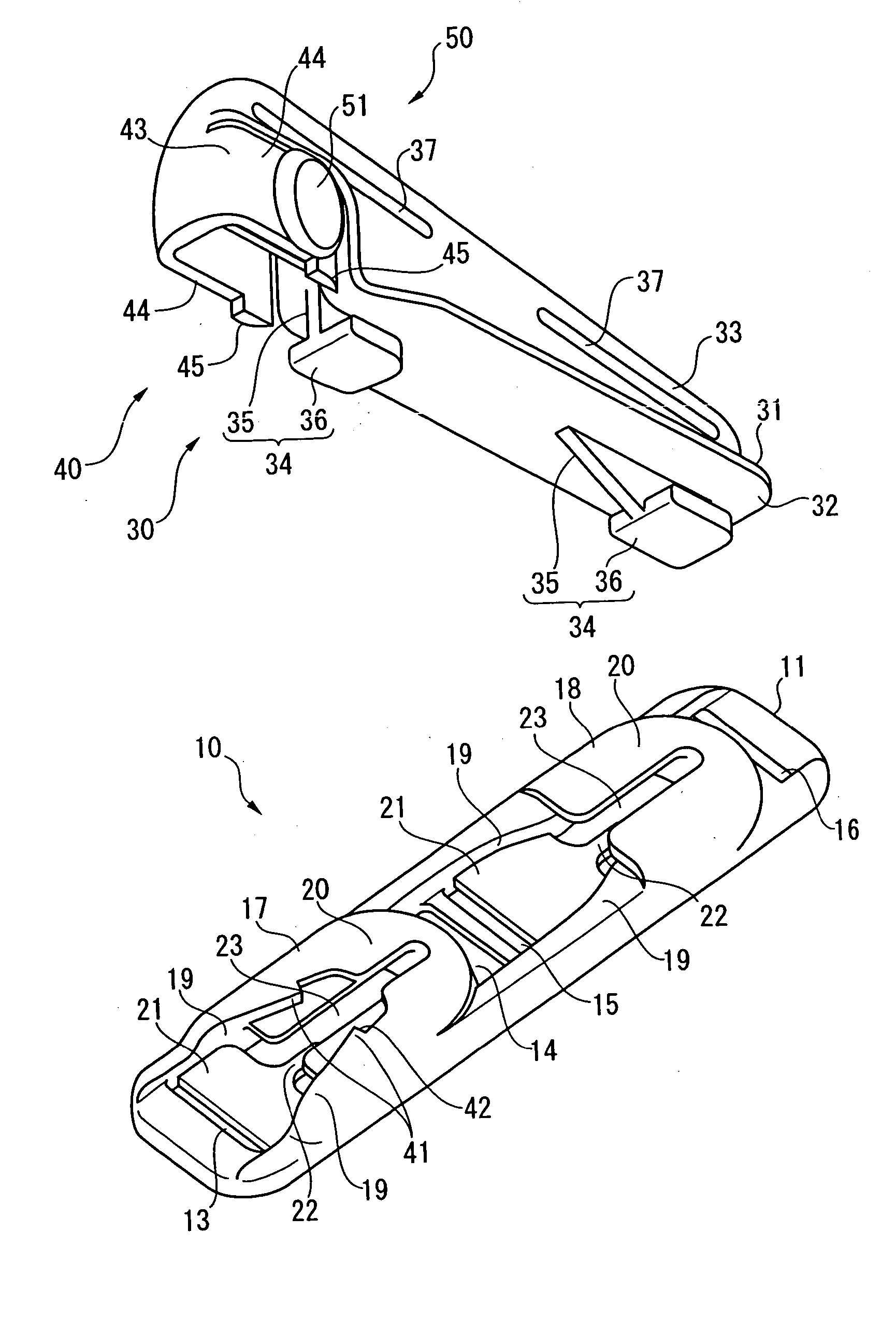
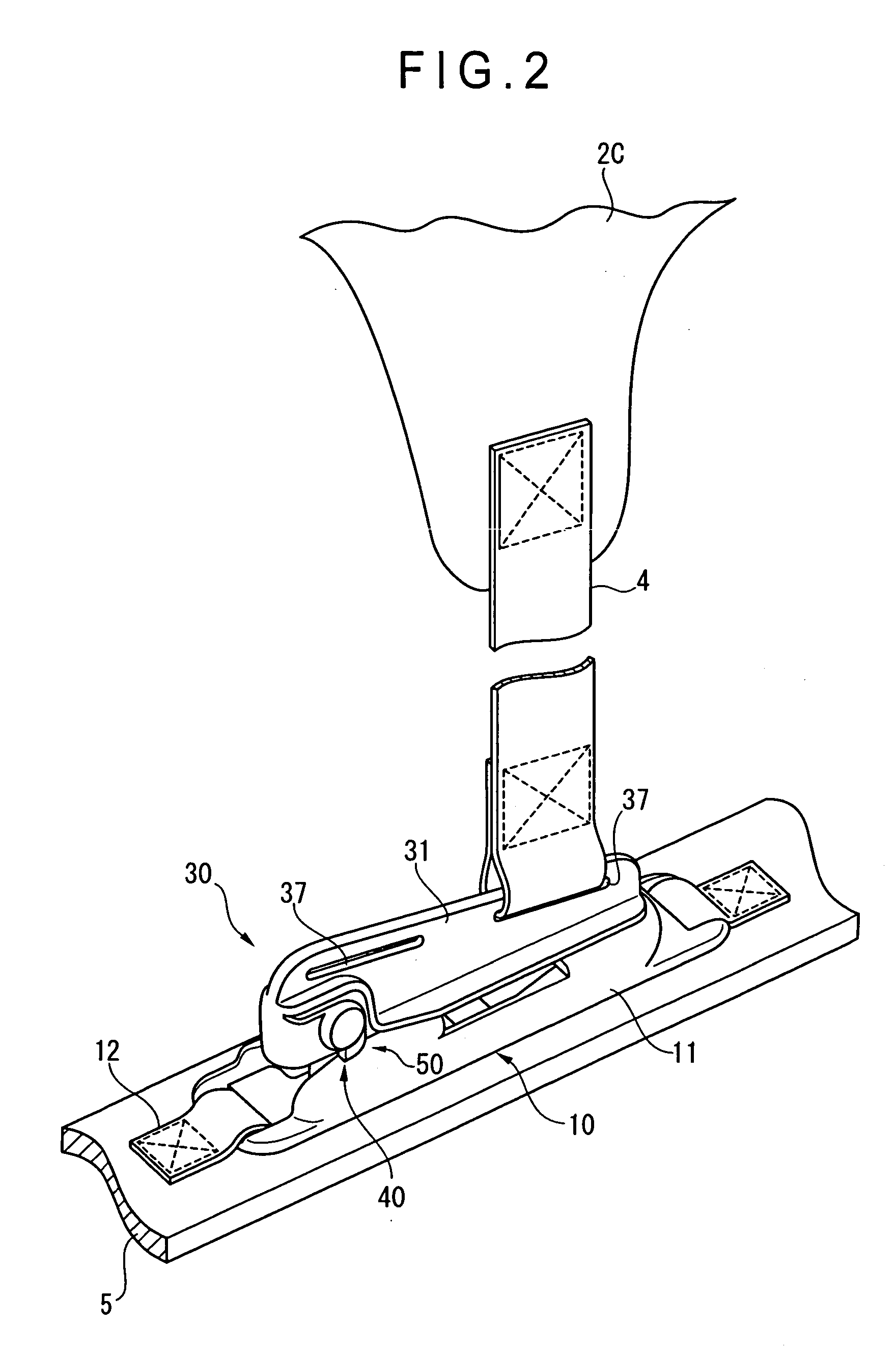
[0027] With this configuration, as the socket has the tape insertion hole formed thereon, the socket can be attached to the one member through the tape insertion hole. The mounting section of the plug is formed as a mounting hole, so that the other member is connected and secured to the plug using the mounting hole. Moreover the mounting hole is opened in the direction intersectional to the inserting direction of the tape as well as to the direction in which the other member receives the tensile force, so that in the state where the tape is orthogonal to the other member, the other member can be inserted into, passed and secured to the plug without being twisted even in a case where the other member is a belt.
[0031] With the configuration, as the buckle has the hooking unit for hooking the plug in the socket, the plug is hooked automatically in the socket just by inserting the plug to the socket to the prespecified position therein. Namely, the movement in the plug extracting direction is restricted. In addition, as the buckle has the releasing unit for releasing the hooking state of the hooking unit, the user can easily unhook the plug from the socket just by operating the releasing unit and releasing the hooking state of the hooking unit.
[0040] In the state described above, in order to unhook the plug from the socket, the user pull out the plug from the socket with a stronger force than a holding force at the holding section of the elastic holding pieces. Thereby the guide walls of the elastic holding pieces are elastically deformed in the direction in which the guide walls move away from each other, and therefore the held pin is released from the holding section. As a result the user can pull out the plug from the socket.
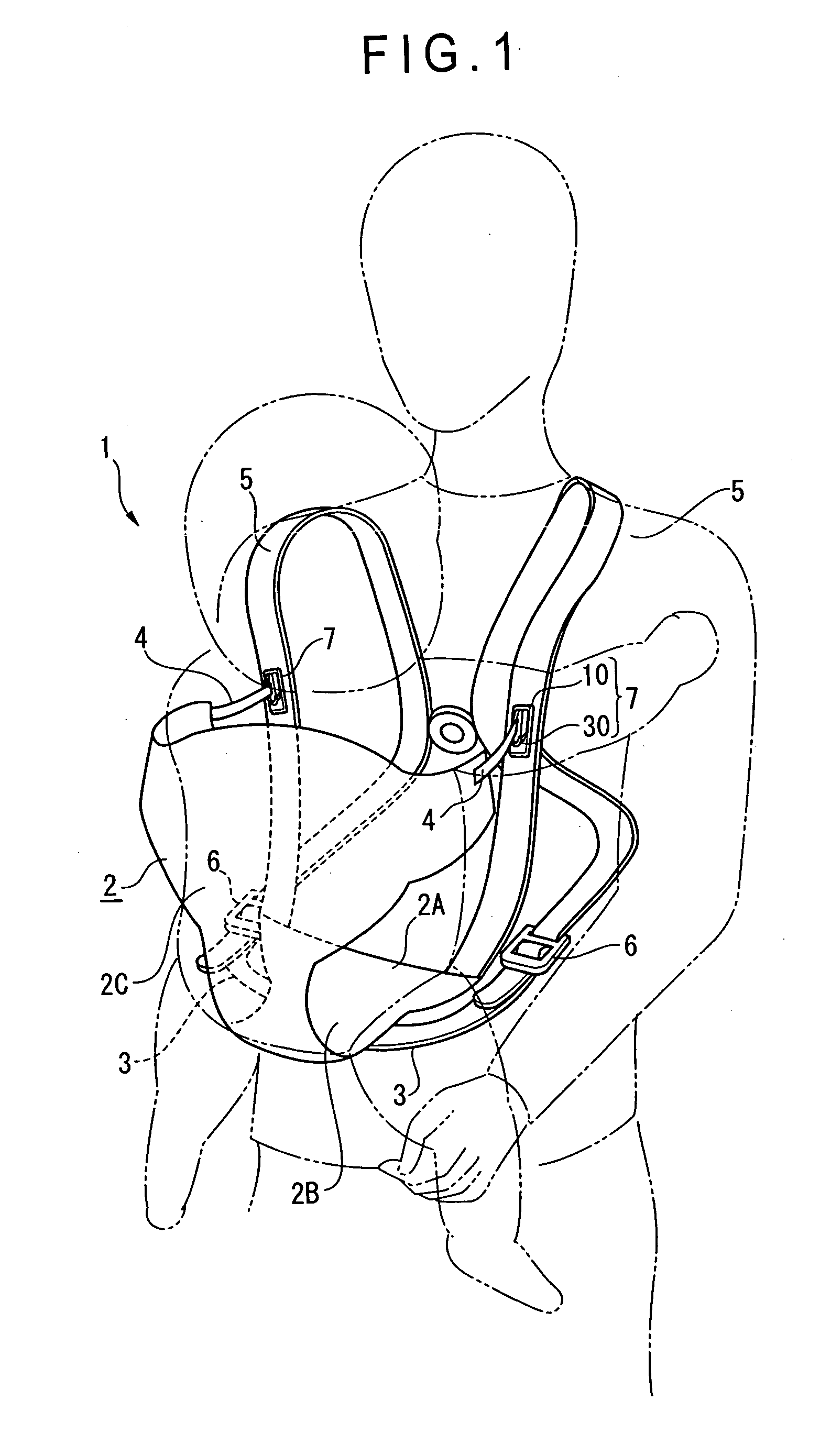
[0042] With the baby carrier described above, there is provided a baby carrier capable of providing the effects and advantages provided by the buckle according to the present invention described above.

Problems solved by technology

However with the conventional buckle, a plug and a socket are attached to tips of a belt member at which the members are coupled to and separated from each other, and a user holds a back end of the socket and makes a front end of the plug inserted to and engaged with the socket or pulled out from the socket, which causes the problem that it can be difficult for a user in a wrong position to insert or pull out the plug.
In a buckle used in a baby carrier, a socket of this type of buckle is attached to a shoulder belt that a user wears it on the user's shoulder, so that it is extremely difficult for the user to hold and insert a back end of a plug to the socket or pull out the plug therefrom.

Method used


Image

  • Buckle and baby carrier using the same
  • Buckle and baby carrier using the same
  • Buckle and baby carrier using the same

Examples


first embodiment

[0059] A first embodiment (an embodiment of a buckle according to the present invention applied to a baby carrier) is illustrated in FIGS. 1 to 10. FIG. 1 is a perspective view showing a baby carrier as a whole; FIG. 2 is an enlarged perspective view showing a buckle; FIG. 3 is an exploded perspective view showing the buckle; FIG. 4 is a view showing a socket and a plug of the buckle in the separated state; FIG. 5 is a plan view showing the socket of the buckle; FIG. 6 is a bottom view showing the plug of the buckle; FIG. 7 is a cross-sectional view showing engagement between the socket and the plug of the buckle; FIG. 8 is a view showing the state shown in FIG. 7 cross-sectioned along line VIII-VIII; FIG. 9 is a view showing the state shown in FIG. 7 cross-sectioned along line IX-IX; and FIG. 10 is a view showing the state shown in FIG. 7 cross-sectioned along line X-X.

[0060] A baby carrier 1 according to the first embodiment includes, as shown in FIG. 1, a carrier body 2, two sho...

second embodiment

[0093] A buckle according to a second embodiment is shown in FIG. 11. FIG. 11 is an exploded perspective view showing the state where a plug 30 and a socket 10 are separated from each other. To explain the second embodiment, the same signs are assigned to the same components as those in the first embodiment and their descriptions are omitted or simplified.

[0094] The buckle according to the second embodiment has a hooking unit and a releasing unit different from that in the first embodiment as shown in FIG. 11.

[0095] A hooking unit 40A according to the second embodiment includes an elastic hooking projection 61 formed on a socket 10 and capable of elastically deforming, and a hooking hole 63 formed on a plug 30 and hooked with the elastic hooking projection 61 when the plug 30 is inserted into the socket 10.

[0096] The elastic hooking projection 61 has a short cylindrical form and is provided on the head side of a guide groove 23 in an engaging projection 18 on the socket 10, and p...

third embodiment

[0101] A buckle according to a third embodiment is shown in FIG. 13 and FIG. 14. FIG. 13 is a perspective view showing the state where a plug 30 is hooked in a socket 10, and FIG. 14 is a perspective view showing the state where the socket 10 and plug 30 are separated from each other. To explain the third embodiment, the same signs are assigned to the same components as those in the first embodiment and descriptions thereof are omitted or simplified.

[0102] A buckle according to the third embodiment has a hooking unit different from that in the first embodiment. While in the first embodiment the guide grooves 23 provided on the socket 10 and the slide sections 34 provided on the plug 30 are provided at two places along the inserting direction of the plug 30 with a space in between, a guide groove and a slide section are provided each at one place in the third embodiment. Further, while the socket 10 is fastened on the shoulder belt 5 with a tape 12 by sewing in the first embodiment,...


PUM


Abstract

A buckle including a pair of members (4, 5) coupled to or separated from each other. The buckle includes a socket (10) and a plug (30) capable of being inserted into the socket and hooked in the socket in the state where the plug is inserted into a prespecified position. The socket is attached to a one member (5) in the pair. The plug has a pull section (33) in the direction intersectional to the plug inserting direction, and a mounting section (37) with the other member mounted thereon is provided on the pull section (33).

Description

BACKGROUND OF THE INVENTION [0001] 1. Field of the Invention [0002] The present invention relates to a buckle and a baby carrier using the buckle. More specifically the present invention relates to a buckle for coupling or separating a pair of members and a baby carrier using the buckle. [0003] 2. Description of Related Art [0004] There has been known a buckle having a socket and a plug capable of being inserted into the socket and hooked in the socket in the state where the plug is inserted into a prespecified position in the socket as a unit for coupling or separating a pair of members to or from each other. [0005] With the buckle having the configuration as described above, a pair of members can be coupled to or separated from each other with a relatively simple operation, so that the buckle is widely used for coupling or separating a belt, a tape, a string, and the like. [0006] For instance, Japanese Patent Laid-Open Publication No. 2004-687 discloses the possibility of forming ...

Claims


Application Information

Patent Timeline
Patent Type & Authority Applications(United States)
IPC IPC(8): A44B11/25A47D13/02A47D13/08
CPCA47D13/025Y10T24/45524Y10T24/4599Y10T24/45796Y10T24/45529Y10T24/45995Y10T24/45958Y10T24/45681A44B11/25A47D15/005
Inventor KANEKO, HITOSHIMINAMI, SAKIKOMORIGUCHI, YUKO
Owner YKK CORP
Learn More