
Method for domain specific test design automation

a test design and automation technology, applied in the field of automatic design of reliability testing, can solve the problems of explicit requirements, lack of automatic testing of implicit content of specification, and failure to scrutinize all the requirements of a specific problem domain associated with the system under development,

Inactive Publication Date: 2005-10-27
MARYLAND UNIV OF +1
View PDF4 Cites 22 Cited by
  • Summary
  • Abstract
  • Description
  • Claims
  • Application Information

AI Technical Summary

Benefits of technology

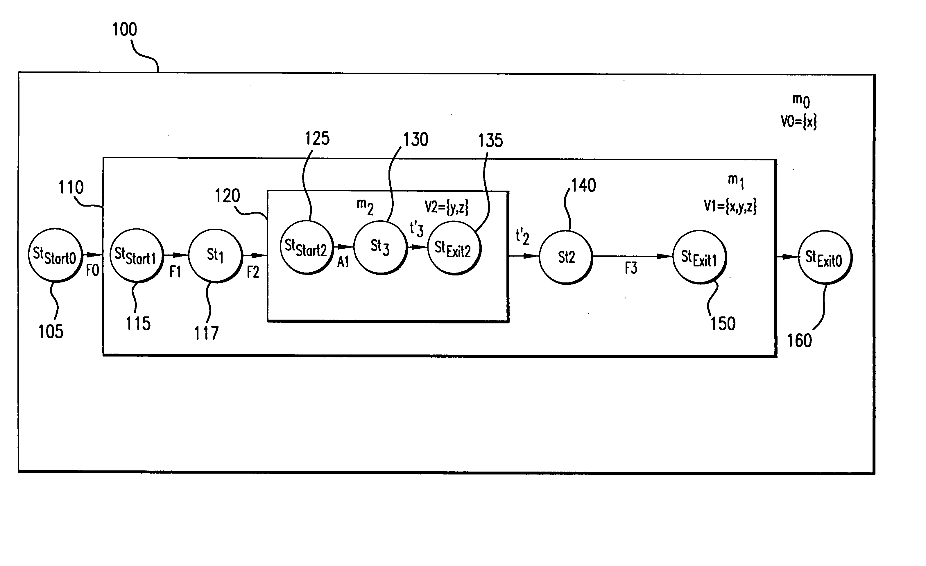
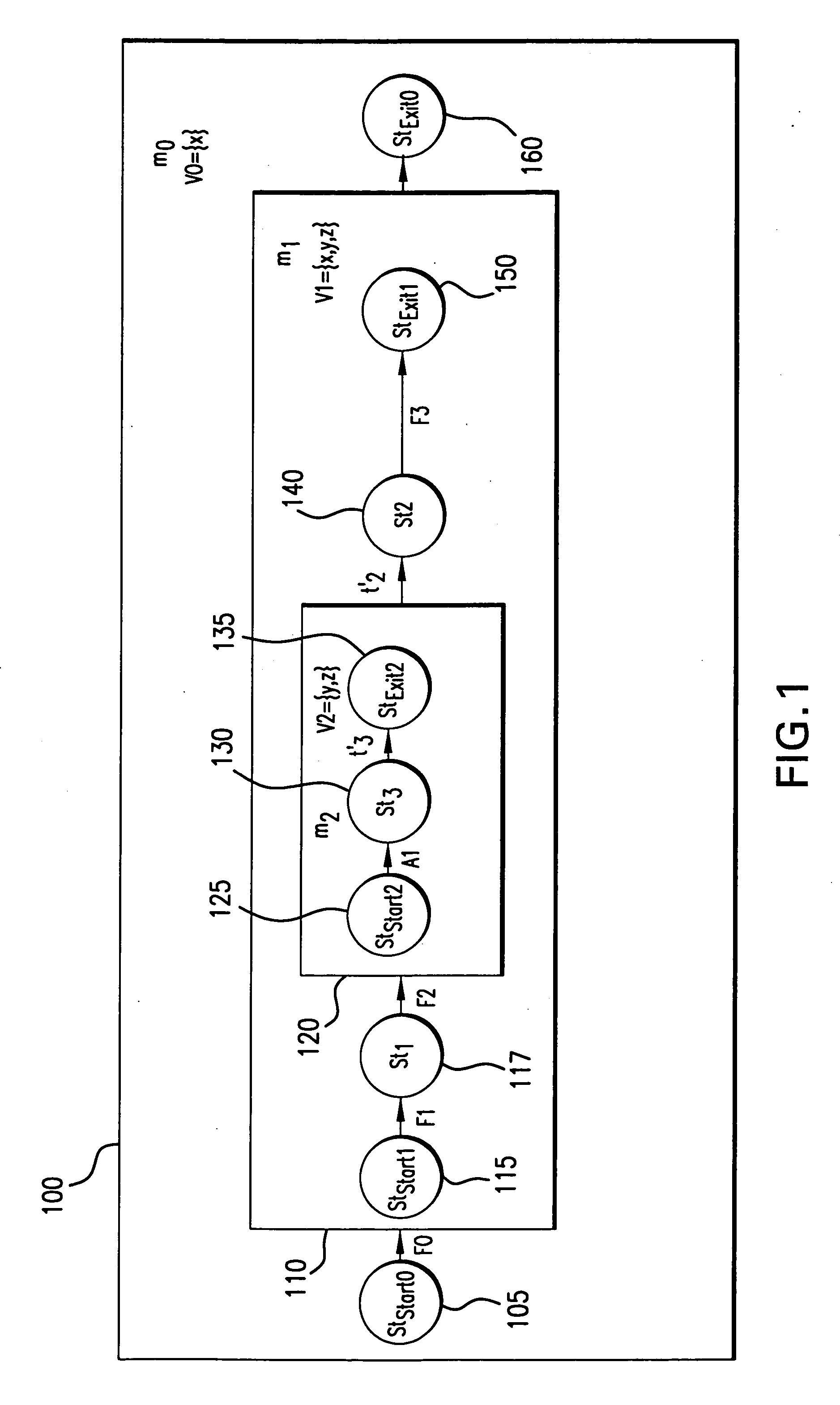
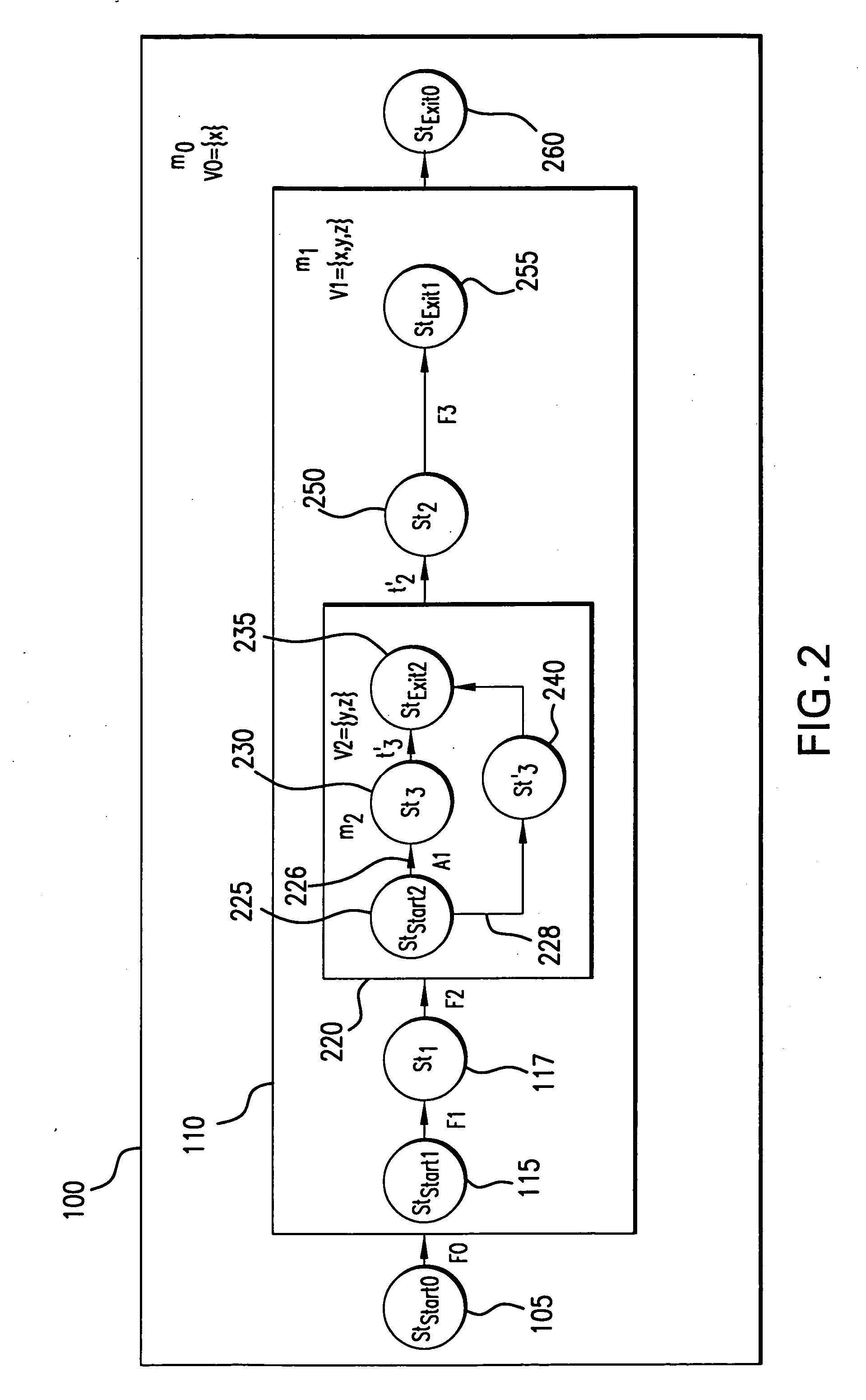
[0011] The present invention provides a method for extracting properties of a domain specific system through the use of a domain specific description language specification. By proper choice of the domain specific language, a set of axioms associated therewith may be carried over to the behavioral model of the application. The method of the present invention extracts the axioms automatically from the domain specific language specification to embed additional test paths in the behavioral model, thereby enhancing the test suite to include test cases which were not explicitly set forth in the formal specification.

Problems solved by technology

However, the automated testing methods that are heretofore available may fail to scrutinize all of the requirements of a specific problem domain associated with the system under development.
Essential, the lack of the ability to automatically test for the implicit content of a specification leaves a gap in a complete reliability test of a system.
It is unlikely that there will be an explicit requirement for the application to handle database related errors such as throwing queries for a non-existent field of the database.
As the modest designs of yesteryear give way to more elaborate systems, the greater chance of error exists in implementing the design.
Whereas, such generalized syntheses of an EFSM from a high-level specification have produced favorable results, such does not insure that a complete set of properties peculiar to the specific problem domain are included in the model.

Method used


Image

  • Method for domain specific test design automation
  • Method for domain specific test design automation
  • Method for domain specific test design automation

Examples


case i

[0057] For the do-notation construct, Order (S)=S′ where S=SDO[F1 . . . Fk] and S′ is the specification reordered by the actual sequence of operation. Thus, S′={F1;F2; . . . ;Fk}.

case ii

[0058] For a composition of functions, Order (S)=S′ where S=SCOMP[F1,F2, . . . ,Fk] and S′={Fk;Fk-1; . . . ;F1;}.

case iii

[0059] For a sequential juxtaposition of functions, Order (S)=S′, where S=SSEQ[F0{F1},F1{G1}, . . . ,Fk]. For a typical specification, a unique start function denoted by F0 is placed at the beginning of the specification. The Order function starts a depth first search (DFS), such as is known in the computing art, from F0 to produce the reordering of functions. Thus, Order (S)=DFS(S, F0)=S′. It should be noted that reordering the sequential juxtaposition of functions unravels the underlying hierarchy in the specification. Thus, S′={F0{F1{G1 . . . ;} . . . ;};}.


PUM


Abstract

A method for automatically generating test cases from a domain specific description language specification makes use of the properties of the language to derive domain specific axioms and language specific predicates. These properties are embedded into an extended finite state machine which is in turn supplied to the input of a test case generator. The enhanced extended finite state machine, referred herein as an extended finite state machine accounting for axioms and predicates (EFSMAP) contains states and transitions associated with information on implied behavior of the specified system within a particular problem domain. The implicit behavior, defined by the axiomatic properties of the operators of the domain specific language, provide test capability of the associated system that was not explicitly set forth in the formal specification, but nevertheless should be tested to increase confidence in the reliability of the finished product.

Description

STATEMENT REGARDING FEDERALLY SPONSORED RESEARCH OR DEVELOPMENT [0001] The development of the invention described herein was funded by the U.S. Government through Contract MDA-904-01-C-0968 granted by the Department of Defense. The U.S. Government has certain rights in this invention.BACKGROUND OF THE INVENTION [0002] 1. Field of the Invention [0003] The present invention is related to the automated design of reliability testing. Specifically, the invention is a specification-based test automation technique that captures implicit domain specific properties in system test models automatically by exploiting type-specific axioms of syntactical relationships between morphemes of domain specific system description languages. [0004] 2. Description of the Prior Art [0005] Reliability test automation is an effective means by which aggressive product deadlines may be met and by which a quality final computing application may be delivered. However, the automated testing methods that are heret...

Claims


Application Information

Patent Timeline
IPC IPC(8): G06F11/00
CPCG06F11/3684
Inventor SINHA, AVIKSMIDTS, CAROL S.
Owner MARYLAND UNIV OF
Learn More