
Dark-banded vial for use with level

a dark banded, vial technology, applied in the field of vials, can solve the problems of putting constraints on the time, difficult to see on a heavily clouded day, at dusk, in poorly lit spaces, prior art attempts have failed to provide a simple and inexpensive, yet successful method of overcoming bubble-locating problems, etc., to achieve the effect of improving the visibility of the bubble and facilitating the locating of the bubbl

Active Publication Date: 2005-10-20
MILWAUKEE ELECTRIC TOOL CORP
View PDF13 Cites 26 Cited by
  • Summary
  • Abstract
  • Description
  • Claims
  • Application Information

AI Technical Summary

Benefits of technology

[0007] It is an object of the invention to provide an improved vial for use in levels which enhances visibility of the bubble therein.
[0008] Another object of the invention is to provide a level utilizing a vial providing increased visibility of the bubble therein.
[0009] Another object of the invention is to provide a method of measuring the levelness of an element including utilizing a vial providing increased visibility of the bubble therein.

Problems solved by technology

While the position of the bubble can readily be seen under normal lighting conditions, it becomes difficult to see on a heavily clouded day, or at dusk, or in poorly lighted spaces.
That is to say, typical conventional levels can be effectively used only in relatively well-lighted environments and, accordingly can put constraints on the times and places craftsmen such as carpenters and bricklayers are able to work efficiently.
Each of these prior art attempts have failed to provide a simple and inexpensive, yet successful method of overcoming bubble-locating problems.
For example, bubble illumination devices may work well in dark conditions, but they provide little assistance when operating in dimly lit or more well lit areas in which the bubble may blend in with the background when viewing the vial.
Floats may increase visibility, but their inclusion in the vial often results in less precise measurements.
Levels including electrical and fiber optic sensing means are typically too expensive and too sensitive to be handled easily at work sites and may not provide any enhancement to viewing the bubble in certain conditions.

Method used


Image

  • Dark-banded vial for use with level
  • Dark-banded vial for use with level
  • Dark-banded vial for use with level

Examples


Embodiment Construction

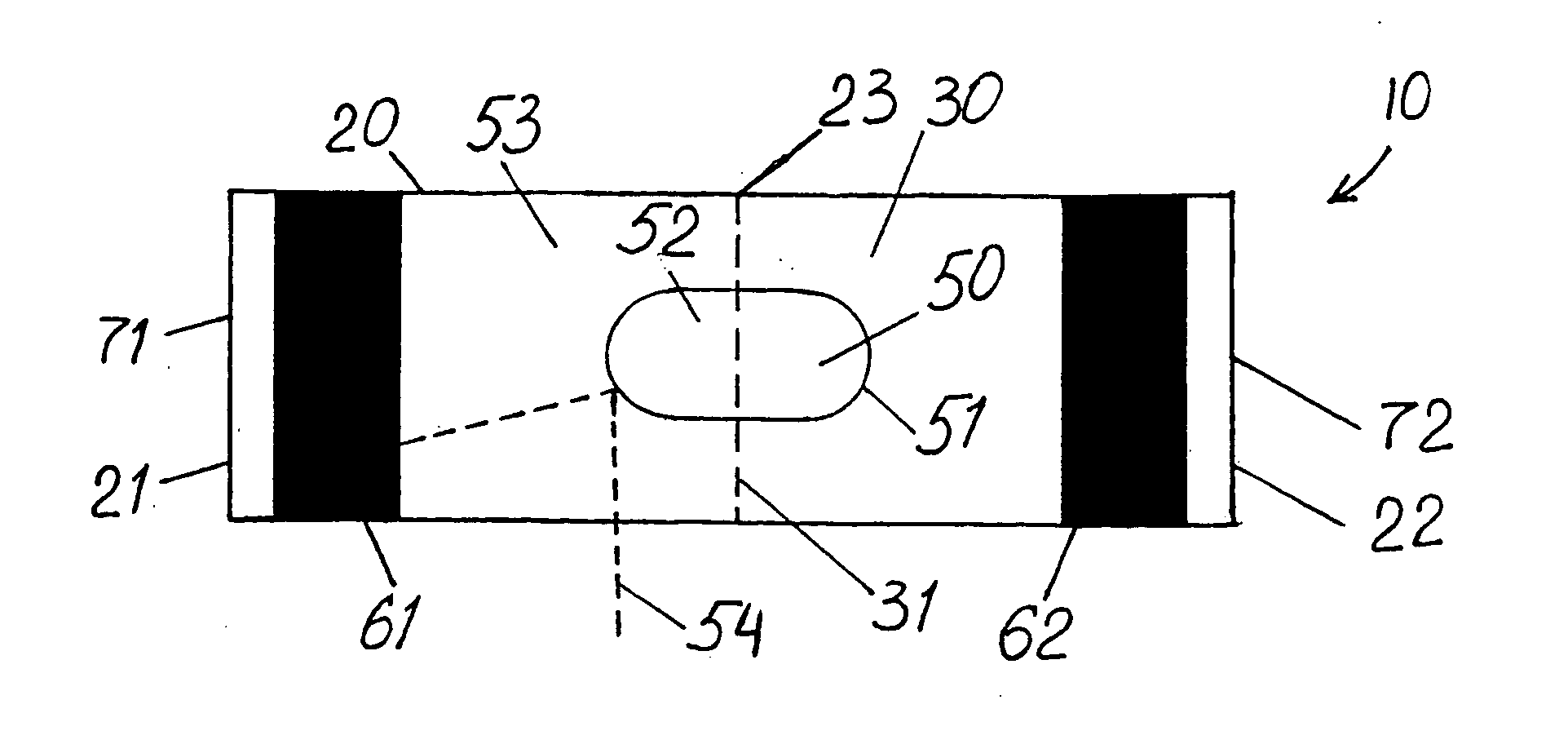
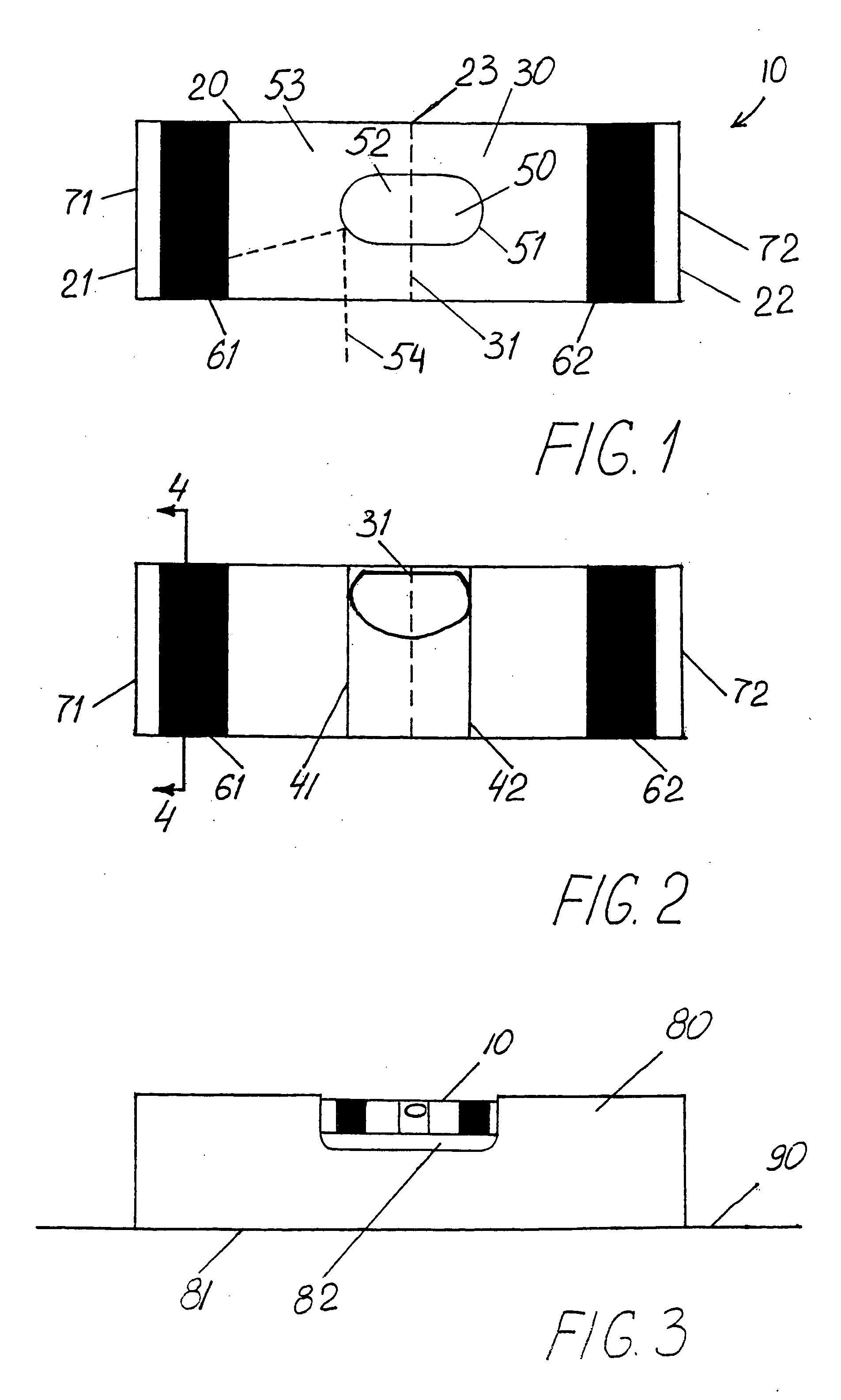
[0035]FIGS. 1 and 2 are overhead views of an embodiment of the vial 10. Vial 10 includes a body 20 having a first end 21 and second end 22 with a midpoint 23 therebetween. Vial 10 is preferably a plastic material such as acrylic, polycarbonate, polystyrene, butyrates or the like, and is transparent. The internal surface of body 20 defines a barrel-shaped cavity 30 such that there exists a cross-section of the cavity 30 which has a maximum diameter. The maximum diameter 31 is preferably positioned near or at the midpoint 23.

[0036] Vial 10 further includes at least one marker ring 40 connected with respect to the body 20, shown as a first marker ring 41 and a second marker ring 42. The marker rings 41,42 are preferably equidistant to the maximum diameter 31. As shown, a bubble 50 is positioned within the cavity 30 at the maximum diameter 31 and between marker rings 41,42. The bubble 50 is defined by a gas-liquid interface 51 with the bubble being gas 52 and the rest of the cavity 30 ...


PUM


Abstract

A vial, level including such vial, and method of using such level are disclosed. The vial comprises a body having first and second ends, a midpoint, and interior and exterior surfaces, at least one marker ring connected with respect to the body, a bubble positioned in the cavity and defined by an interface, and first and second dark-colored bands circumscribing the cavity. The vial enhances the visibility of the bubble through the reflection of the first and second bands on the interface such that the interface along the perimeter of the bubble appears dark-colored.

Description

FIELD OF THE INVENTION [0001] This invention is related generally to vials and, more particularly, to vials enclosing a bubble for use in levels. BACKGROUND OF THE INVENTION [0002] It has long been known to utilize the effect of gravity on fluids having different densities to determine the levelness of elements such as building components, machines, lines, poles, etc. Spirit levels, also called bubble levels, are well known instruments utilizing gravity in this way to set horizontal or vertical surfaces. Such levels include a sealed vial containing a bubble, typically air, floating in a non-freezing liquid, usually mineral spirits. The measured surface is considered horizontal or vertical when the air bubble rests between predetermined graduated marks on the vial. [0003] The accuracy with which a horizontal or vertical plane can be determined is critically dependent on the accuracy at which the bubble is centered between the transverse marks on the vial which, of course, is dependen...

Claims


Application Information

Patent Timeline
IPC IPC(8): G01C9/24G01C9/32G01C9/34
CPCG01C9/34G01C9/32
Inventor FORAN, THOMAS P.
Owner MILWAUKEE ELECTRIC TOOL CORP
Learn More