
Expandable bone device

a bone device and expandable technology, applied in the field of expandable bone devices, can solve the problems of inconvenient control of the expansion of the balloon-like device, the inability to control the expansion direction of the cancellous bone and/or the reduction of the compression fracture, and the inability to reduce the compression fractur

Active Publication Date: 2005-10-13
CORELINK
View PDF10 Cites 394 Cited by
  • Summary
  • Abstract
  • Description
  • Claims
  • Application Information

AI Technical Summary

Benefits of technology

[0009] The expandable bone device may include one or more of the following features. For example, the support surfaces may be arranged in one or more pairs of support surfaces that expand transversely outwards in opposite directions symmetrically or non-symmetrically with respect to the longitudinal axis. Some of the narro...

Problems solved by technology

Inflation of the balloon-like device causes a compaction of the cancellous bone and / or bone marrow against the inner cortical wall of the bone, thereby resulting in enlargement of the bone cavity and / or reduction of the compression fracture.
However, it has been found that expansion of the balloon-like device is not readily controllable.
As a result, the direction of compaction of the cancellous bone and / or reduction of the compression fracture is not controllable, and expansion occurs in multiple directions and along multiple axes.

Method used


Image

  • Expandable bone device
  • Expandable bone device
  • Expandable bone device

Examples


Embodiment Construction

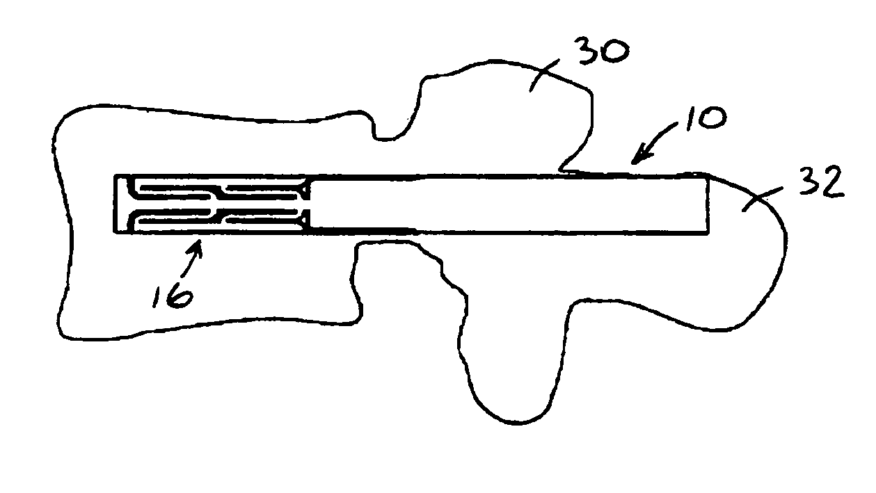
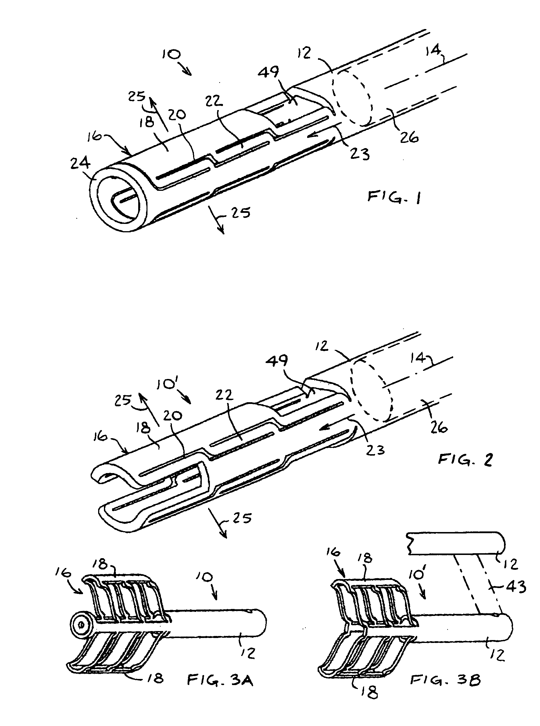
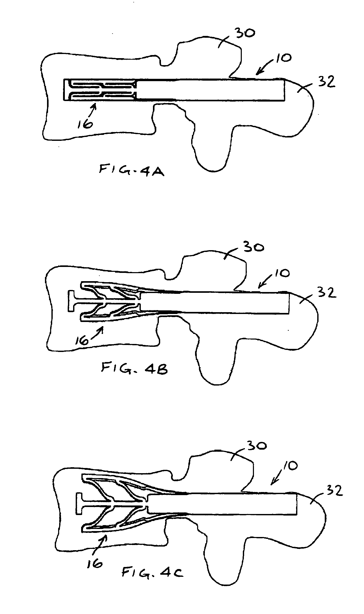
[0026] Reference is now made to FIG. 1, which illustrates an expandable bone device 10, constructed and operative in accordance with an embodiment of the present invention.

[0027] The expandable bone device 10 may include a unitary body 12 extending along a longitudinal axis 14. Device 10 may include a deformable distal end portion 16 having a collapsed orientation for placement adjacent a spinal structure. The deformable distal end portion 16 may include relatively wide, mutually contiguous support surfaces 18 outlined by relatively narrow cutouts 20. The support surfaces 18 are contiguous with the rest of the unitary body 12 via relatively narrow deformable splines 22.

[0028] In the illustrated, non-limiting embodiment of FIG. 1, unitary body 12 may be generally cylindrical in shape (although any other shape is also in the scope of the invention) and may include a non-deformable endpiece 24 distal to the deformable distal end portion 16. The non-deformable endpiece 24 may be a rin...


PUM

PropertyMeasurementUnit
Angleaaaaaaaaaa
Structureaaaaaaaaaa
Shapeaaaaaaaaaa

Abstract

An expandable bone device including a unitary body extending along a longitudinal axis and including a deformable distal end portion having a collapsed orientation for placement adjacent a spinal structure, the deformable distal end portion including relatively wide, mutually contiguous support surfaces outlined by relatively narrow cutouts, the support surfaces being contiguous with the rest of the unitary body via relatively narrow deformable splines, the deformable distal end portion having an expanded orientation wherein the support surfaces are moved transversely outwards away from and generally parallel to the longitudinal axis, and an actuator coupled to the deformable distal end portion and operative to cause movement of the deformable distal end portion between the collapsed orientation and the expanded orientation.

Description

FIELD OF THE INVENTION [0001] The present invention relates generally to expandable bone devices, such as but not limited to, devices for vertebral body reconstruction (vertebroplasty), such as for treatment of compression fractures of the thoracic and lumbar spine area, or for an expandable bone device for transversely displacing structures associated with the spine, for example. BACKGROUND OF THE INVENTION [0002] Various instruments and methods for the treatment of compression-type bone fractures and other osteoporotic and / or non-osteoporotic conditions have been developed. In one method, a cavity may be formed in the bone to be treated, followed by the insertion of an inflatable balloon-like device into the bone cavity. Inflation of the balloon-like device causes a compaction of the cancellous bone and / or bone marrow against the inner cortical wall of the bone, thereby resulting in enlargement of the bone cavity and / or reduction of the compression fracture. The balloon-like devic...

Claims


Application Information

Patent Timeline
IPC IPC(8): A61B17/00A61B17/68A61B17/70A61B17/72A61B17/88A61F2/00A61F2/28A61F2/30A61F2/44A61F2/46
CPCA61B17/70A61F2310/00796A61B17/8858A61B2017/00539A61B2017/00544A61B2017/00557A61B2017/00867A61F2/4455A61F2002/2835A61F2002/30092A61F2002/30179A61F2002/30579A61F2002/30785A61F2002/30787A61F2002/4475A61F2210/0014A61F2230/0058A61F2310/00017A61F2310/00023A61B17/7266A61F2002/30593
Inventor LEVY, MARK M.GREENBERG, ILAN
Owner CORELINK
Learn More