
Implantable prosthetic heart valve comprising a valve body and a tubular vascular graft

a heart valve and tubular vascular technology, applied in the field of prosthetic heart valves, can solve the problems of affecting the normal functioning of the atrioventricular orifice and heart operation, accumulation of blood in the heart cavity or the regurgitation of blood past the valve, damage to the heart muscle,

Inactive Publication Date: 2005-10-06
CARBOMEDICS
View PDF11 Cites 89 Cited by
  • Summary
  • Abstract
  • Description
  • Claims
  • Application Information

AI Technical Summary

Problems solved by technology

Resulting defects in the valves hinder the normal functioning of the atrioventricular orifices and operation of the heart.
More specifically, defects such as the narrowing of the valve opening (valvular stenosis) or the defective closing of the valve (valvular insufficiency) result in an accumulation of blood in a heart cavity or regurgitation of blood past the valve.
If uncorrected, prolonged valvular stenosis or valvular insufficiency can cause damage to the heart muscle, which may eventually necessitate total valve replacement.
However, in many patients, once degeneration of a valve has occurred, it may occur that surrounding blood vessels are also diseased.
However, this required a relatively long duration of surgery, and the quality of stitching could only be tested in vivo after implantation, making leaks difficult to detect and potentially deleterious to the well-being of the patient.
A drawback of this configuration is that the valve size has to be reduced in order to accommodate the additional bulk of the graft end.
This results in a restriction in the available flow area, with associated resistance to flow.
Thus, any decrease in the internal diameter of the valve is undesirable, as it reduces the volume of blood that can be pumped with the available heart muscle.

Method used


Image

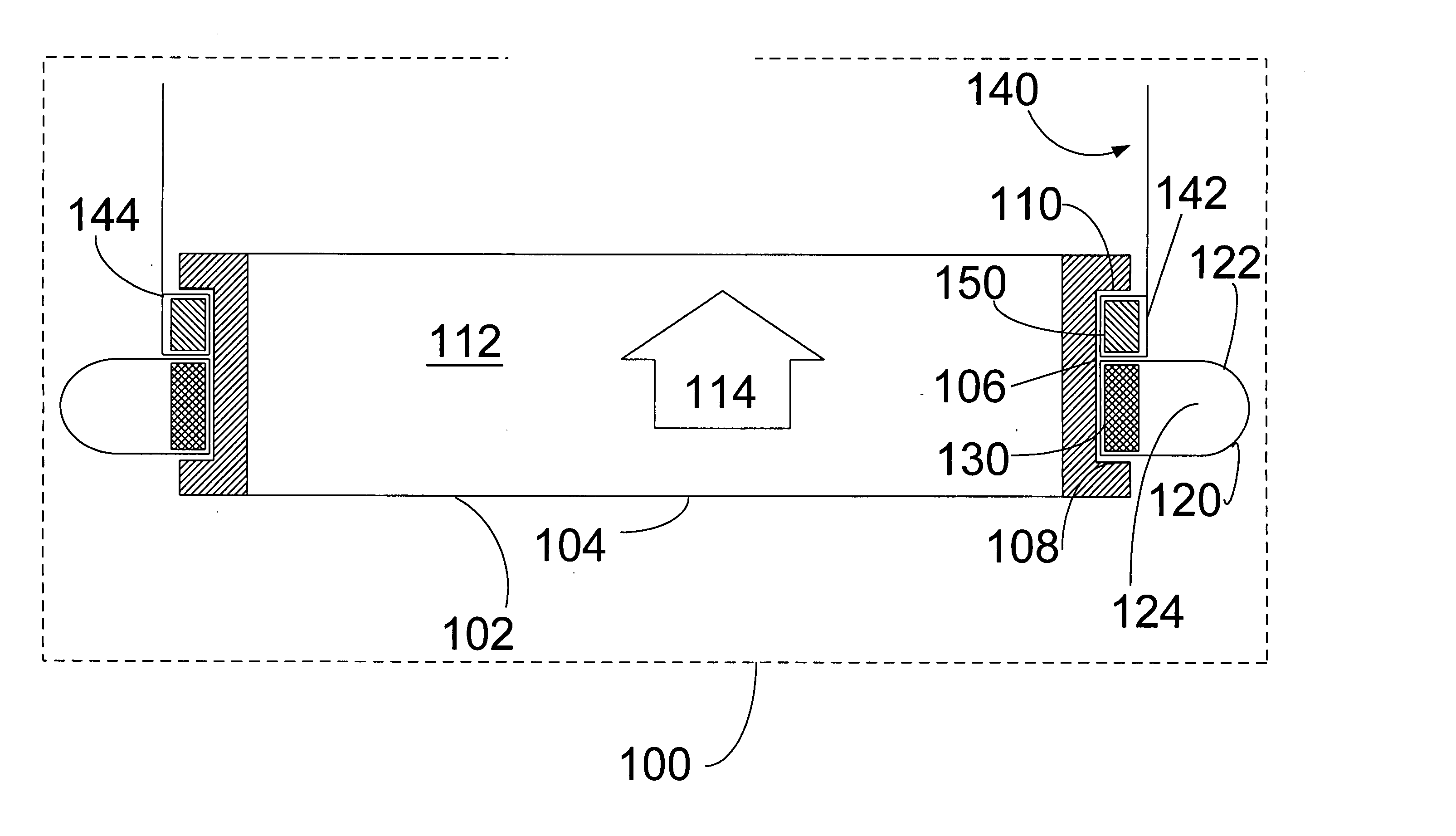
  • Implantable prosthetic heart valve comprising a valve body and a tubular vascular graft
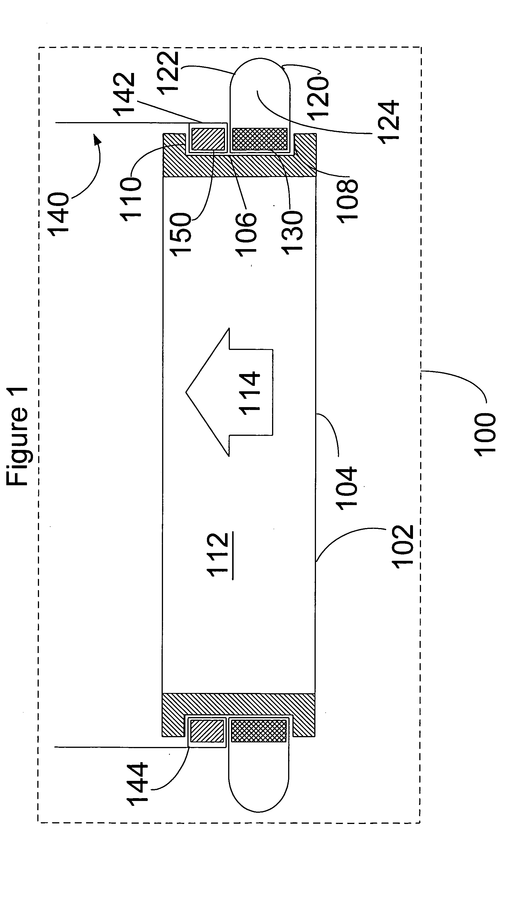
  • Implantable prosthetic heart valve comprising a valve body and a tubular vascular graft
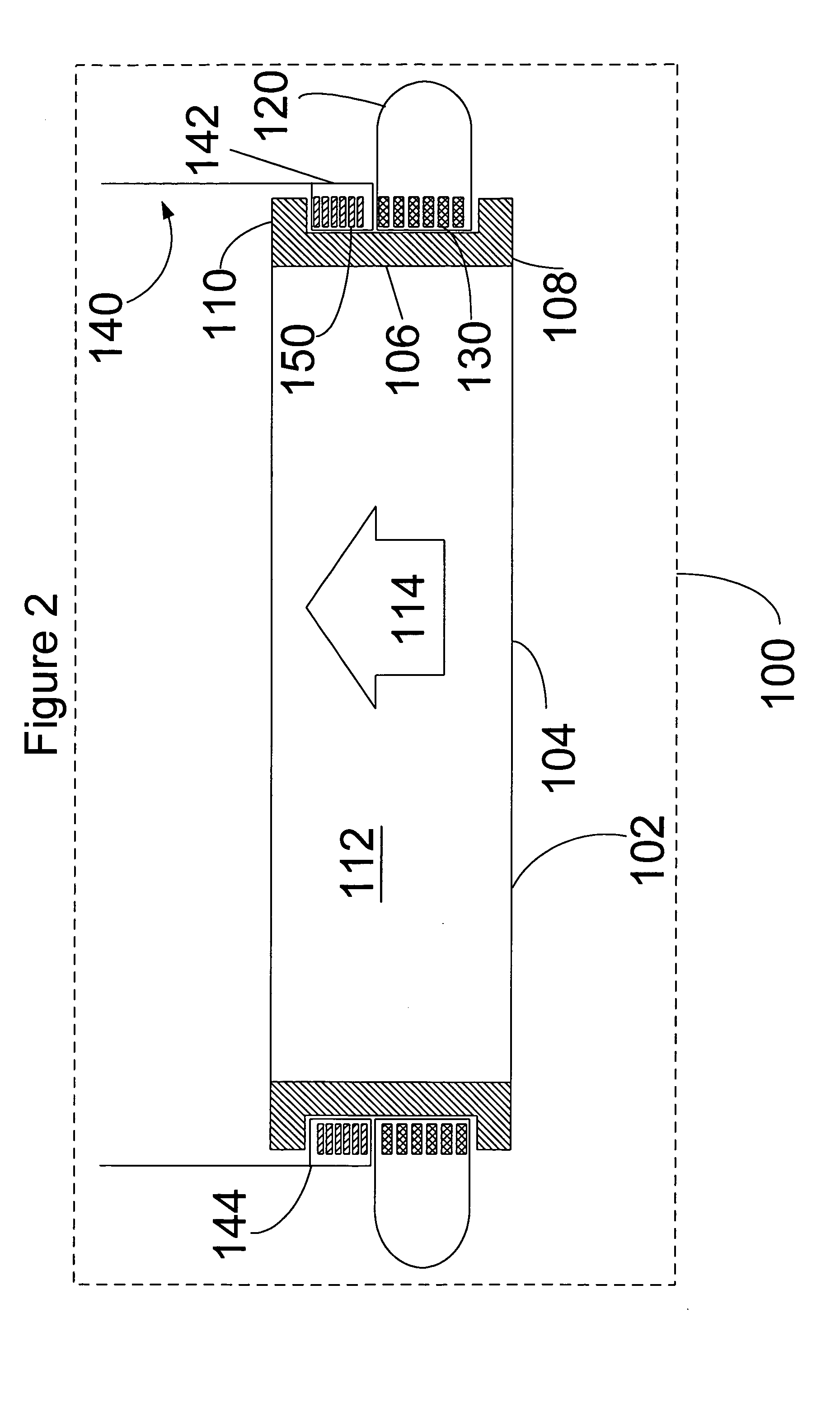
  • Implantable prosthetic heart valve comprising a valve body and a tubular vascular graft

Examples


Embodiment Construction

[0021] The present invention will now be described with reference to the attached figures. The words and phrases used herein should be understood and interpreted to have a meaning consistent with the understanding of those words and phrases by those skilled in the relevant art. No special definition of a term or phrase, i.e., a definition that is different from the ordinary and customary meaning as understood by those skilled in the art, is intended to be implied by consistent usage of the term or phrase herein. To the extent that a term or phrase is intended to have a special meaning, i.e., a meaning other than that understood by skilled artisans, such a special definition will be expressly set forth in the specification in a definitional manner that directly and unequivocally provides the special definition for the term or phrase.

[0022] The present invention relates to an implantable prosthetic heart valve, suitable for replacing a heart valve present in a valve annulus.

[0023] O...


PUM


Abstract

We disclose an implantable prosthetic heart valve, comprising: a valve body comprising an orifice member, wherein the orifice member comprises an external groove; a sewing cuff; a sewing cuff retaining member seated within the external groove of the orifice member and coupling the sewing cuff to the orifice member; a tubular vascular graft; and a graft retaining member seated within the external groove of the orifice member and coupling the tubular vascular graft to the orifice member.

Description

BACKGROUND OF THE INVENTION [0001] The present invention relates generally to the field of prosthetic heart valves. More particularly, it concerns prosthetic heart valves combined with a tubular vascular graft. [0002] In the mammalian heart, deoxygenated blood flows into the right atrium through the superior vena cava and the inferior vena cava. Upon contraction of the right atrium, the deoxygenated blood flows into the right ventricle. When the right ventricle contracts, the deoxygenated blood is pumped through the pulmonary artery to the lungs. Oxygenated blood returning from the lungs enters the left atrium. From the left atrium, the oxygenated blood flows into the left ventricle, which in turn pumps oxygenated blood to the body via the aorta and lesser arteries branching thereoff. [0003] This pumping action is repeated in a rhythmic cardiac cycle in which the ventricular chambers alternately contract and pump, then relax and fill. As is well known, a series of one-way cardiac va...

Claims


Application Information

Patent Timeline
Patent Type & Authority Applications(United States)
IPC IPC(8): A61F2/24
CPCA61F2/2403A61F2/2409
Inventor SAUTER, JOSEPH A.
Owner CARBOMEDICS
Learn More