Diffraction grating and laser television using the same

a technology of laser television and diffraction grating, which is applied in the field of diffraction grating, can solve the problems of high coherence of light beams, loss of intensity of different light beams, and sparkle noise generation, and achieve the effect of preventing the generation of sparkle nois

Active Publication Date: 2005-10-06
SAMSUNG ELECTRONICS CO LTD
View PDF4 Cites 8 Cited by
  • Summary
  • Abstract
  • Description
  • Claims
  • Application Information

AI Technical Summary

Benefits of technology

[0010] Therefore, the present invention has been made in view of the above mentioned problems incurred in the related art, and an object of the invention is to provide a diffraction grating to prevent generation of sparkle noise in a laser TV adapted to reproduce an image on a screen by light beams of different wavelengths.

Problems solved by technology

However, these light beams have a high coherency, so that an irregular intensity distribution is exhibited when the light beams reproduce an image on a display or screen.
Such sparkle noise may be produced as a result of many factors, such as surface non-uniformity of the display or screen (on which an image is displayed by the light beams), and / or fine dust present in optical paths (along which the laser beams travel), and other factors.
However, there is a problem in that the different light beams exhibit a loss of intensity after passing through the ground glass plates.
However, diffraction gratings for reducing or removing sparkle noise have the disadvantage of requiring a plurality of diffraction gratings, each having different grating periods corresponding to the respective wavelengths of the coherent light beams, which increases complexity and manufacturing costs and requires complex optical axis alignment due to use of a plurality of diffraction gratings.

Method used


Image

  • Diffraction grating and laser television using the same
  • Diffraction grating and laser television using the same
  • Diffraction grating and laser television using the same

Examples


Embodiment Construction

[0015] Now, preferred embodiments of the present invention will be described in detail with reference to the annexed drawings. In the following description of the present invention, a detailed description of known functions and configurations incorporated herein will be omitted when it may make the subject matter of the present invention unclear.

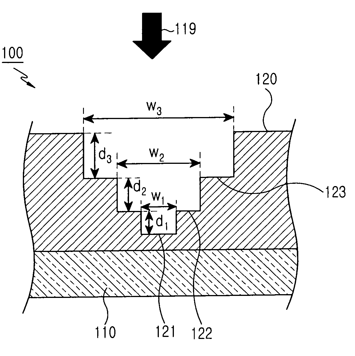
[0016]FIG. 1 is a cross-sectional view to explain a structure of a diffraction grating according to a first embodiment of the present invention. The diffraction grating 100 includes a substrate 110, and a grating member 120 formed on the substrate 110 having a stepped structure. The arrow 19 indicates the direction of incidence of light beams upon the diffraction grating 100. The grating member 120 preferably has a plurality of steps 121, 122, and 123. The number of steps in the grating member 120 can be an odd number corresponding to 3 or more to provide an odd phase structure as will be described below. Each of the steps 121, 122, and 123...


PUM


Abstract

A diffraction grating including a substrate, and a grating member formed on the substrate, the grating member having a stepped structure including steps, the number of which corresponds to an odd number greater than or equal to three to provide an odd phase structure. The heights of the steps of the grating member are determined such that the light beams diffracted by their corresponding steps substantially have a phase difference of π with reference to a diffracted light beam of a reference wavelength.

Description

PRIORITY [0001] This application claims priority to an application entitled “DIFFRACTION GRATING AND LASER TELEVISION USING THE SAME” filed in the Korean Intellectual Property Office on Apr. 1, 2004 and assigned Serial No. 2004-22530, the contents of which are hereby incorporated by reference. BACKGROUND OF THE INVENTION [0002] 1. Field of the Invention [0003] The present invention relates to a diffraction grating, and more particularly to a diffraction grating having a structure to control a sparkling phenomenon occurring in an image-reproducing apparatus due to a laser source. [0004] 2. Description of the Related Art [0005] Generally, image-reproducing apparatuses such as projection televisions (TVs) and laser TVs, in order to produce various colors on a screen, use lasers capable of producing light beams of different wavelengths, with corresponding colors, such as red, green and blue. Color images are produced by combining the above-mentioned light beams of different wavelengths,...

Claims


Application Information

Patent Timeline
Patent Type & Authority Applications(United States)
IPC IPC(8): G01B11/02G02B5/18H04N5/74H04N9/31
CPCG02B5/18H04N9/3129H04N5/7416H04N9/31
Inventor AHN, PIL-SOOPAVEL, SERAFIMOVICHEONG, BYOUNG-HOMUN, YONG-KWEUNLEE, JIN-HO
Owner SAMSUNG ELECTRONICS CO LTD
Why Eureka
Try Eureka