Blood vessel holding and positioning system

a positioning system and blood vessel technology, applied in the field of blood vessel holding and positioning system, can solve the problems of affecting the overall time of the cabg procedure, and cannot be achieved by conventional holding mechanisms

Inactive Publication Date: 2005-09-22
MEDTRONIC INC
View PDF6 Cites 8 Cited by
  • Summary
  • Abstract
  • Description
  • Claims
  • Application Information

AI Technical Summary

Benefits of technology

[0011] One embodiment of the invention relates to a device used to hold and position a blood vessel in the performance of a coronary artery bypass graft procedure. The device has a handle and an attachment head coupled to the handle. The attachment head has a collar adapted to substantially encircle a blood vessel, the collar having a number of suction apertures. The device further has a vacuum port adapted to be coupled to a vacuum source, the vacuum port communicating a suction to the suction apertures to hold the blood vessel.

Problems solved by technology

One challenge in performing a CABG procedure is holding and orienting the graft vessel when suturing the graft to the anastomosis site.
Conventional holding mechanisms, such as a clip or forceps, or even an endoscopic robotic grasper in the case of minimally invasive cardiac surgery may not be specifically designed to hold the graft and therefore may be awkward to use, possibly lengthening the overall time of the CABG procedure.
Further, ideally the open end of the graft should be held in an open position to facilitate suturing the graft to the anastomosis site, which may not be accomplished by conventional holding mechanisms, such as an alligator clip, that grasp the vessel.
Further still, conventional holding mechanisms may not be designed to specifically avoid damaging the graft vessel.
In particular, while the surgeon can manually use a delicate hold on the vessel when utilizing a forceps in an open heart procedure, a robotic grasper used in an endoscopic procedure may not provide direct feedback to the surgeon with respect to the force applied to the vessel when grasping, and therefore may damage the graft vessel.
Conventional holding instruments such as clips and forceps are not designed to hold the graft vessel securely with another surgical instrument inside the graft vessel because a clip or forceps will typically close off the lumen inside the vessel that is needed to accommodate the additional surgical instrument.

Method used


Image

  • Blood vessel holding and positioning system
  • Blood vessel holding and positioning system
  • Blood vessel holding and positioning system

Examples


Embodiment Construction

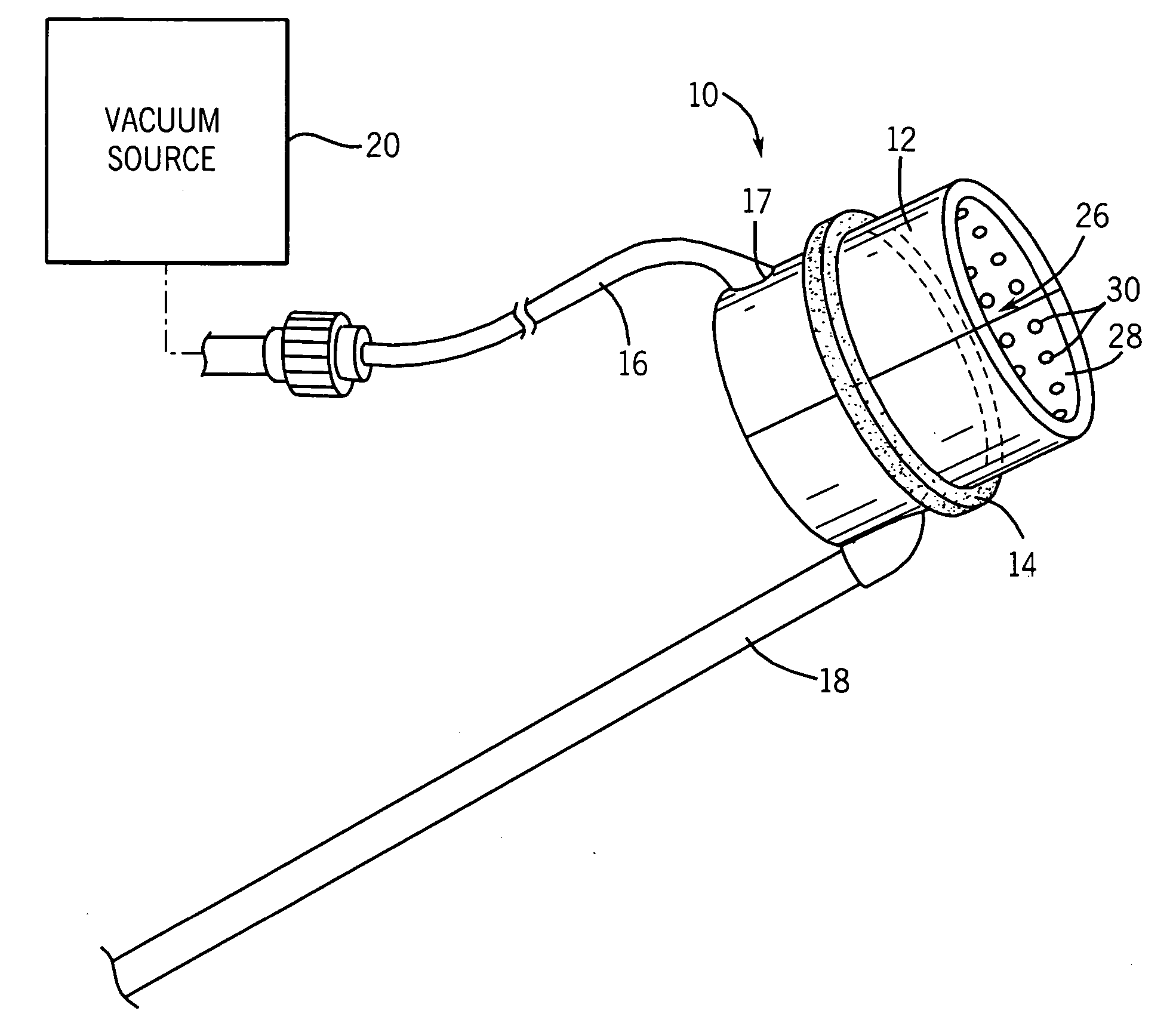
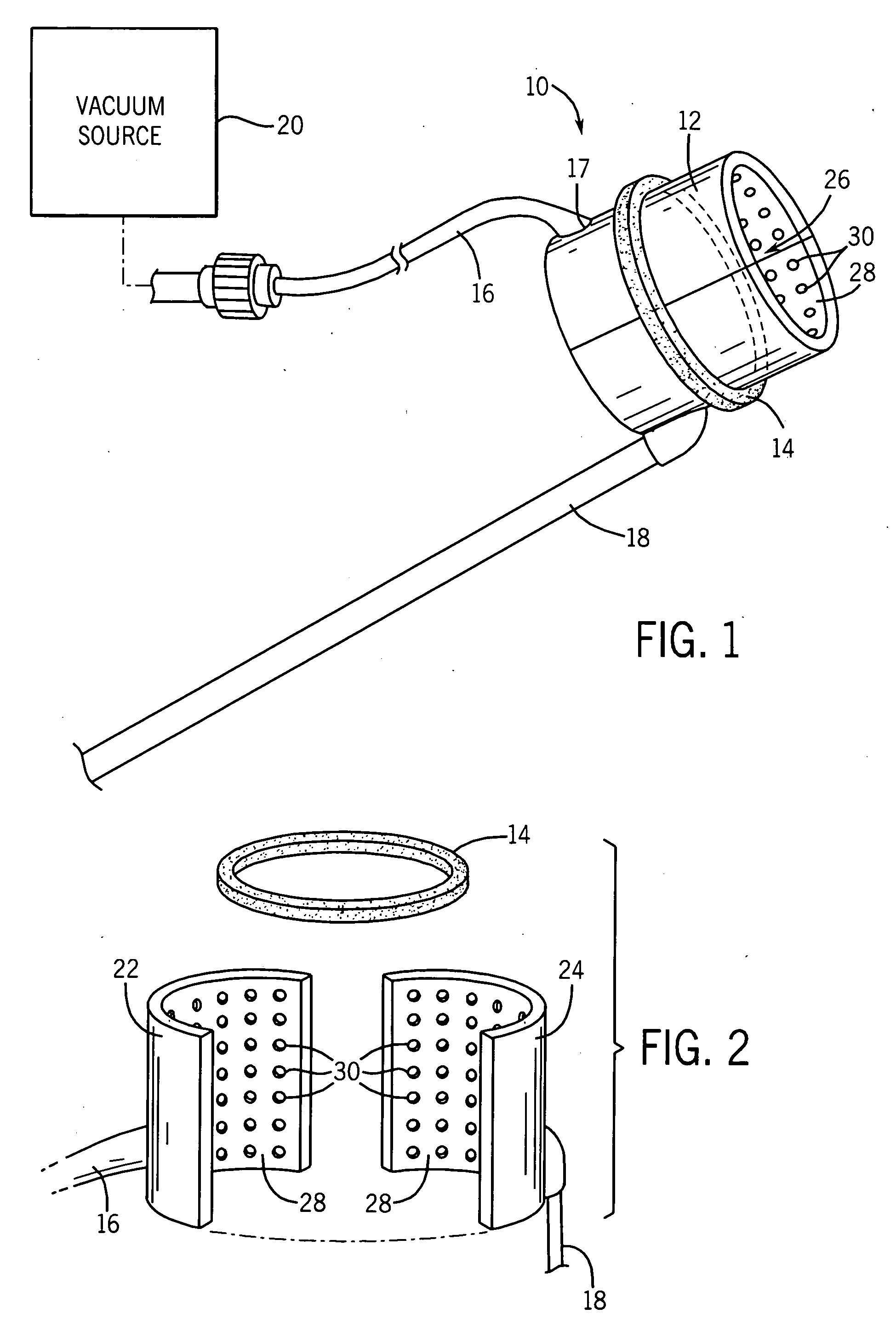
[0027] Referring to FIG. 1, according to an exemplary embodiment, a conduit holding and positioning device, shown as device 10, has a collar or cuff, shown as vacuum collar 12, and a handle, shown as positioning rod 18. A coupling mechanism or ring, shown as grasping ring 14, is disposed around vacuum collar 12. A vacuum line 16 extends from a vacuum port 17 that may be located directly on the vacuum collar 12. An interior lumen 26 having a lumen wall 28 extends through the vacuum collar 12. The lumen wall has a number of vacuum holes 30.

[0028] Further referring to FIG. 1, the vacuum line 16 may be coupled to a vacuum source 20. The vacuum source 20 may be a spring-loaded syringe sufficient to provide a suction at vacuum holes 30. In other embodiments, the vacuum source 20 may be an electrically powered vacuum pump or any other device known in the art that is able to provide a suction on vacuum line 16. While the vacuum line 16 is shown in FIG. 1 as a separate conduit extending fro...


PUM


Abstract

A device used to hold and position a blood vessel in the performance of a coronary artery bypass graft procedure includes a handle and an attachment head coupled to the handle. The attachment head has a collar adapted to substantially encircle the blood vessel and having a number of suction apertures. A vacuum port is adapted to be coupled to a vacuum source and communicates a suction to the suction apertures to hold the blood vessel.

Description

FIELD OF THE INVENTION [0001] The present invention relates to a device configured to atraumatically hold a blood vessel or other conduit during the performance of a surgical procedure. In particular, the present invention relates to a device that holds a graft vessel used to create an anastomosis during a coronary artery bypass graft procedure while presenting the open end of the graft in a configuration suitable for suturing at the anastomosis site. BACKGROUND OF THE INVENTION [0002] A coronary artery bypass graft (CABG) procedure may be used in the treatment of coronary artery disease to bypass an obstruction in a coronary artery, thereby providing adequate blood flow to downstream heart tissues, lessening the risk of myocardial infarction. [0003] Typical blood vessels used for the graft in a CABG procedure include an internal mammary artery (IMA), a greater saphenous vein (GSV) from the patient's leg, or a radial artery. The graft vessel is utilized as a shunt to avoid an obstru...

Claims


Application Information

Patent Timeline
Patent Type & Authority Applications(United States)
IPC IPC(8): A61B17/00A61B17/11A61B17/30A61B19/00
CPCA61B17/30A61B2017/306A61B2017/1107A61B2017/00778
Inventor GUENST, GARY W.OLIG, CHRISTOPHER
Owner MEDTRONIC INC
Why Eureka
Try Eureka