Composite material, structure and polycrystalline structure film and method of making particles
a technology of polycrystalline structure and composite materials, applied in the field of composite materials, structure and polycrystalline structure films and the method of making particles, can solve the problems that the size and/or dispersion of crystalline cores cannot be sufficiently controlled in the ultra thin film, the enlargement of crystalline grains, and the inability to include magnetic materials in the nanoholes, etc., to achieve reliable and uniform filling of magnetic materials, reduce the size of crystalline grains, and reliable control of size
- Summary
- Abstract
- Description
- Claims
- Application Information
AI Technical Summary
Benefits of technology
Problems solved by technology
Method used
Image
Examples
first embodiment
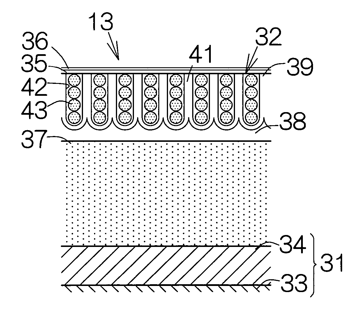
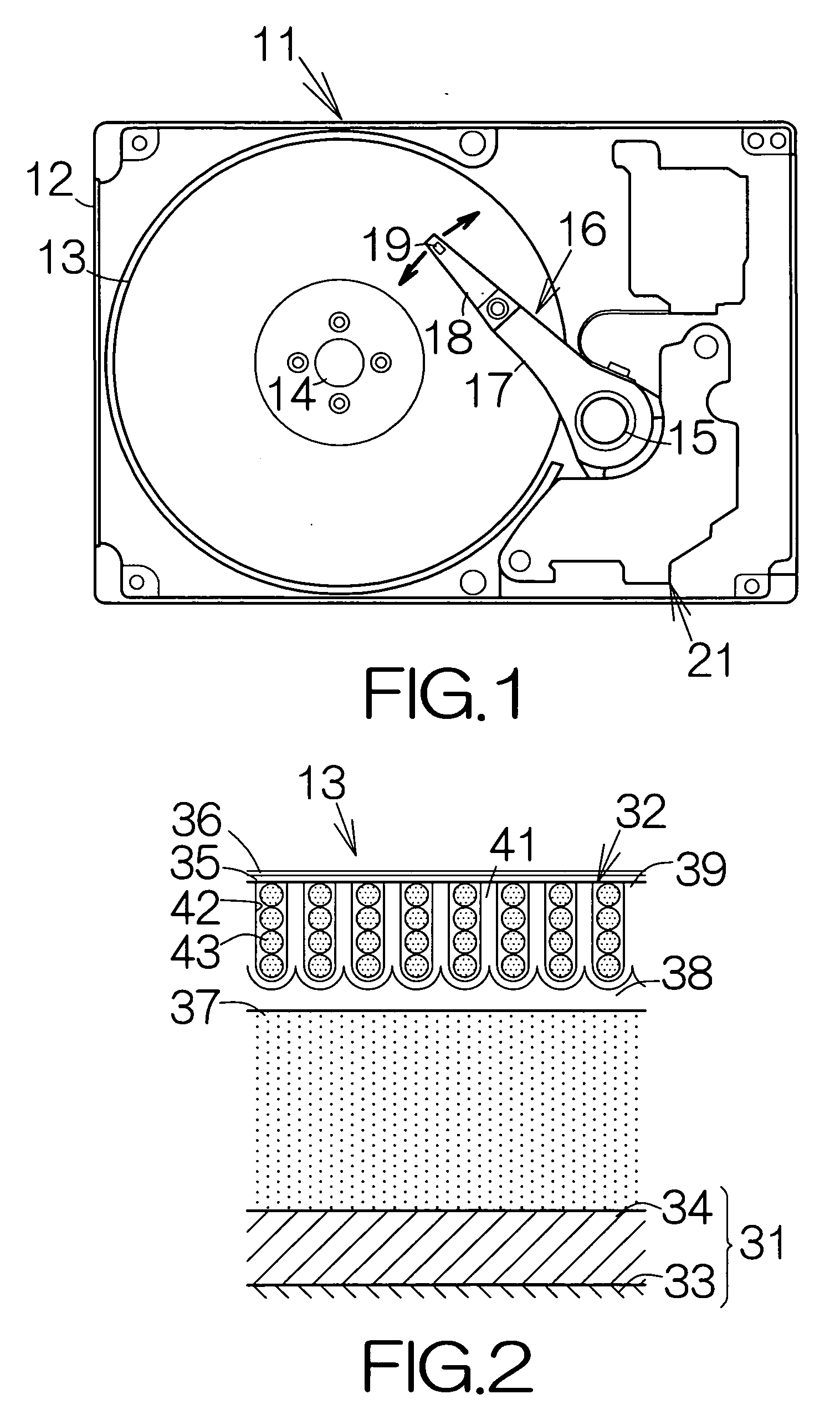
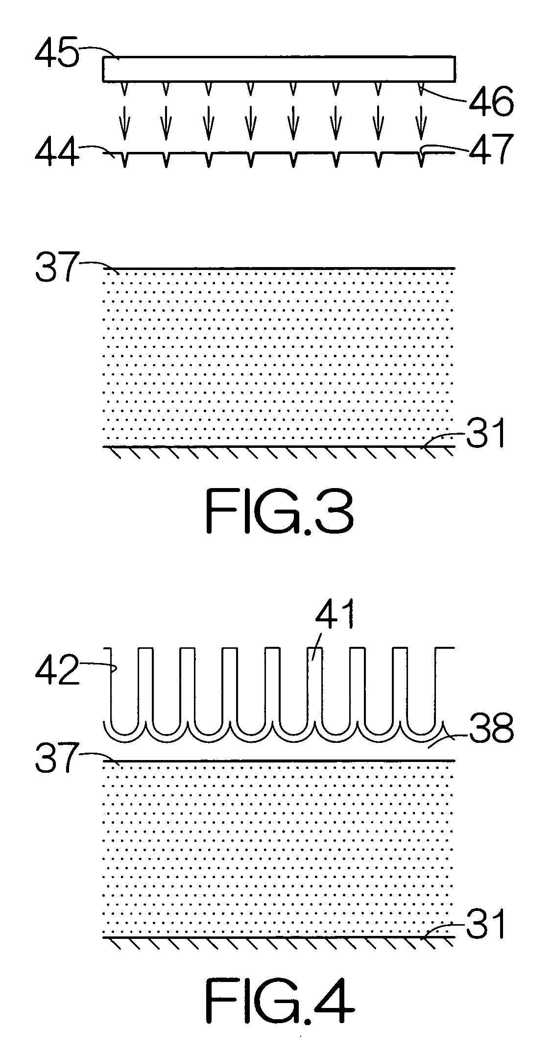
[0059]FIG. 2 illustrates a vertical sectional view of the magnetic recording disk 13 according to the present invention. The magnetic recording disk 13 belongs to a so-called perpendicular magnetic recording medium. The magnetic recording disk 13 includes a substrate 31 as a support member and a multilayered structure film 32 extending on the front and back surfaces of the substrate 31. The substrate 31 may comprise a disk-shaped Si body 33 and amorphous SiO2 films 34 extending on the front and back surfaces of the Si body 33. Alternatively, a glass substrate, an aluminum substrate, a ceramic substrate, or the like, may be employed as the substrate 31. Magnetic information is recorded in the multilayered structure film 32. A protection overcoat 35 such as a diamond-like-carbon (DLC) film and a lubricating agent film 36 such as a perfluoropolyether (PFPE) film may be formed to cover over the surface of the multilayered structure film 32.
[0060] The multilayered structure film 32 inclu...
second embodiment
[0078]FIG. 7 illustrates the vertical sectional view of a magnetic recording disk 13a according to the present invention. The magnetic recording disk 13a belongs to a so-called perpendicular magnetic recording medium. The magnetic recording disk 13a includes a substrate 51 as a support member and multilayered structure films 52 extending on the front and back surfaces of the substrate 51. The substrate 51 may comprise a disk-shaped Si body 53 and amorphous SiO2 films 54 extending on the front and back surfaces of the Si body 53. Alternatively, a glass substrate, an aluminum substrate, a ceramic substrate, or the like, may be employed as the substrate 51. Magnetic information is recorded in the multilayered structure films 52. A protection overcoat 55 such as a diamond-like-carbon (DLC) film and a lubricating agent film 56 such as a perfluoropolyether (PFPE) film may be formed to cover over the surface of the multilayered structure film 52.
[0079] The multilayered structure film 52 in...
third embodiment
[0095]FIG. 12 illustrates a vertical sectional view of the magnetic recording disk 13b according to the present invention. The magnetic recording disk 13b belongs to a so-called perpendicular magnetic recording medium. The magnetic recording disk 13b includes a substrate 71 as a support member and polycrystalline structure films 72 extending on the front and back surfaces of the substrate 71. A glass substrate may be employed as the substrate 71, for example. Alternatively, an aluminum substrate, a silicon substrate, a ceramic substrate, or the like, may be employed as the substrate 71. Magnetic information is recorded in the polycrystalline structure films 72. A protection overcoat 73 such as a diamond-like-carbon (DLC) film and a lubricating agent film 74 such as a perfluoropolyether (PFPE) film may be formed to cover over the surface of the polycrystalline structure film 72.
[0096] The polycrystalline structure film 72 includes minute particles or nanoparticles 75 existing on the ...
PUM
| Property | Measurement | Unit |
|---|---|---|
| diameter | aaaaa | aaaaa |
| diameter | aaaaa | aaaaa |
| diameter | aaaaa | aaaaa |
Abstract
Description
Claims
Application Information
 - R&D
- Intellectual Property
- Life Sciences
- Materials
- Tech Scout
- Unparalleled Data Quality
- Higher Quality Content
- 60% Fewer Hallucinations
Browse by: Latest US Patents, China's latest patents, Technical Efficacy Thesaurus, Application Domain, Technology Topic, Popular Technical Reports.
© 2025 PatSnap. All rights reserved.Legal|Privacy policy|Modern Slavery Act Transparency Statement|Sitemap|About US| Contact US: help@patsnap.com


