
Innerduct guide tube assembly for fiber optic cable

a fiber optic cable and guide tube technology, applied in the field of tubular conduits, can solve the problems of difficult to simply insert a second cable into a conduit that already contains a first cable, many unused or “dead” space within such a conduit, and the inability to insert the second cabl

Inactive Publication Date: 2005-09-08
MILLIKEN & CO
View PDF8 Cites 49 Cited by
  • Summary
  • Abstract
  • Description
  • Claims
  • Application Information

AI Technical Summary

Problems solved by technology

While such conduit provides excellent protection for communication cable, there is also much unused or “dead” space within such a conduit.
However, it has been found that it is difficult to merely insert a second cable into a conduit that already contains a first cable.
When a rope is blown into a conduit already containing a cable, or a second cable is “snaked” through the conduit, they are often impeded by the first cable, making it impossible to insert the second cable.
A problem has been encountered in that when conduit is placed over long distances or within buildings, corners, curves and undulations will invariably occur therein.

Method used


Image

  • Innerduct guide tube assembly for fiber optic cable
  • Innerduct guide tube assembly for fiber optic cable
  • Innerduct guide tube assembly for fiber optic cable

Examples


Embodiment Construction

[0016] 1. 4×6 Nylon Tubing

Inside Diameter4mmOutside Diameter6mmPull String, A&E210TPlenum Cable3mmPull Length60fta. Straight0.5 to 0.7 lbsb. Two 90 deg bends0.7 to 0.9 lbsc. Four 90 deg bends1.2 to 1.4 lbs

Note:

bends had a 8″ radius

[0017] 2. 4×6 Nylon Tubing

Inside Diameter4mmOutside Diameter6mmPull String, A&E300TPlenum Cable3mmPull Length300fta. Straight1.6 to 2.0 lbsb. Two 90 deg bends2.4 to 2.9 lbsc. Four 90 deg bends3.4 to 4.0 lbs

Note:

bends had a 12″ radius

[0018] 3. 3.3×5 Nylon Tubing

Inside Diameter3.3mmOutside Diameter5mmPull String, A&E210TPlenum Cable3mmPull Length80fta. Straight3.1 to 3.9 lbsb. Two 90 deg bends3.7 to 4.1 lbsc. Four 90 deg bends6.5 to 7.5 lbs

Note:

bends had a 12″ radius

[0019] 4. 3.3×5 Nylon Tubing

Inside Diameter3.3mmOutside Diameter5mmPull String, A&E210TPlenum Cable3mmPull Length150fta. Straight7.5 to 8.5 lbs

Note:

due to confimed space this was not a entirely straight run

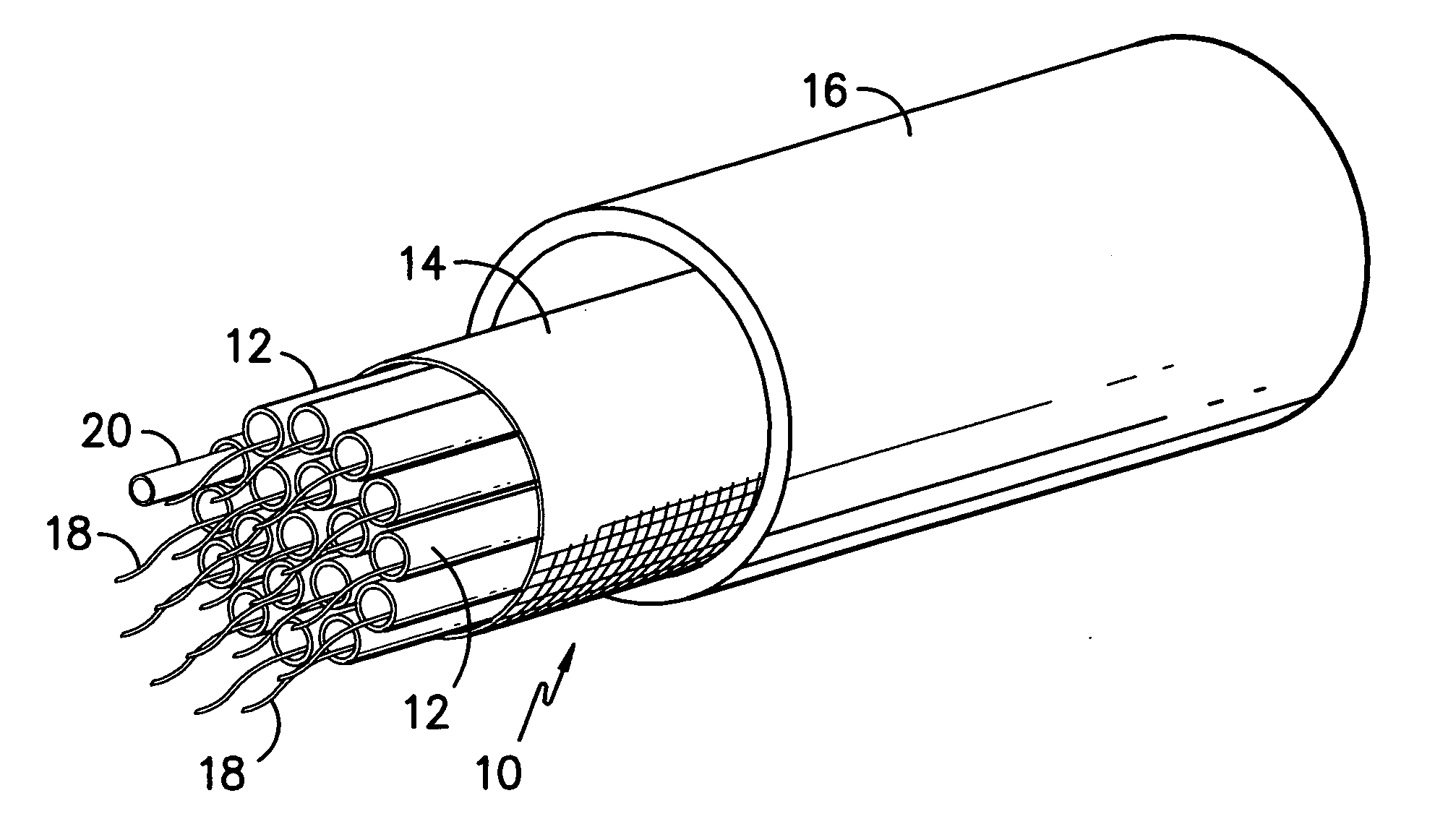
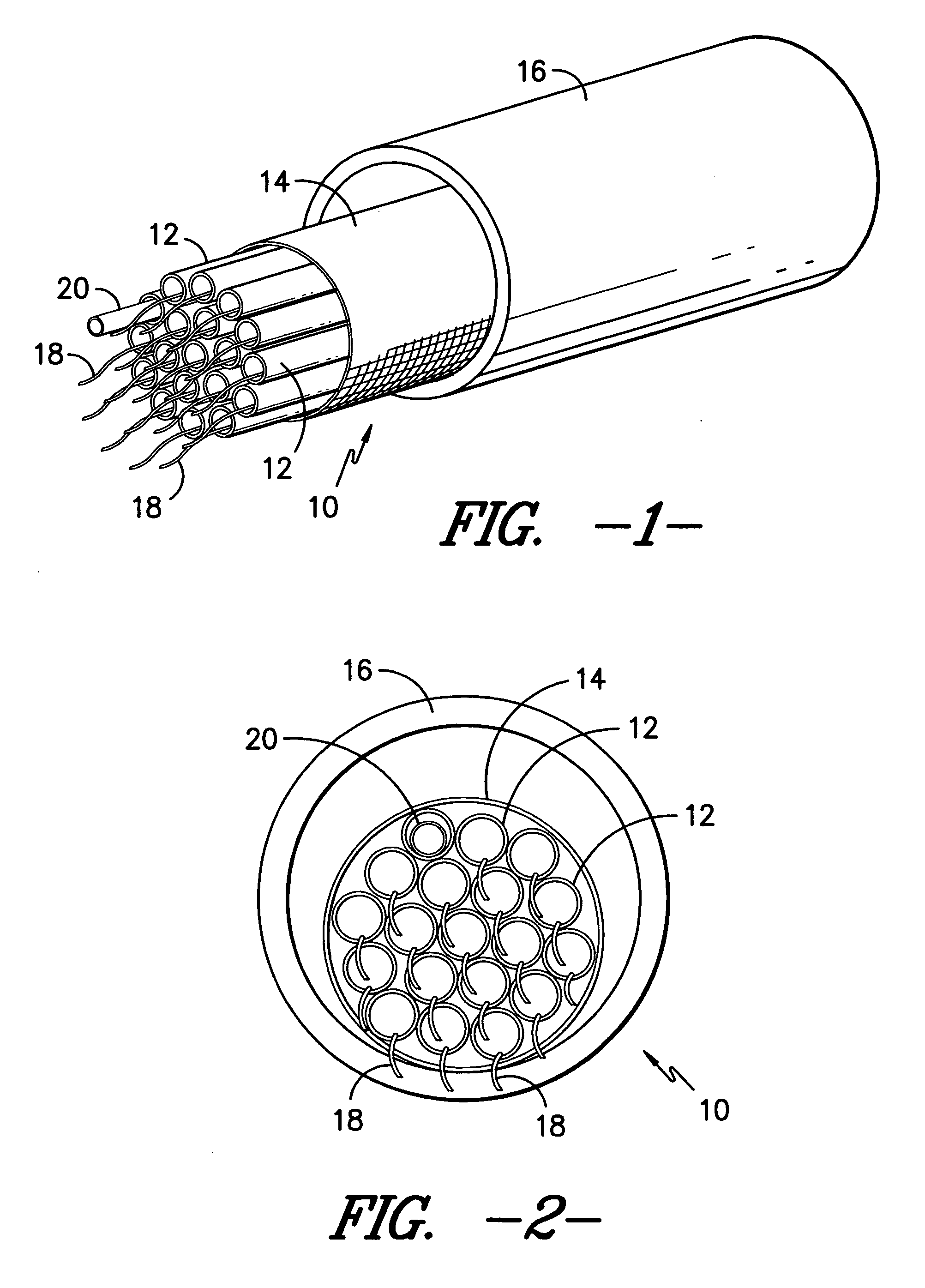
[0020] The textile sleeve 14 is used to protect the bundle of guide tubes 1...


PUM


Abstract

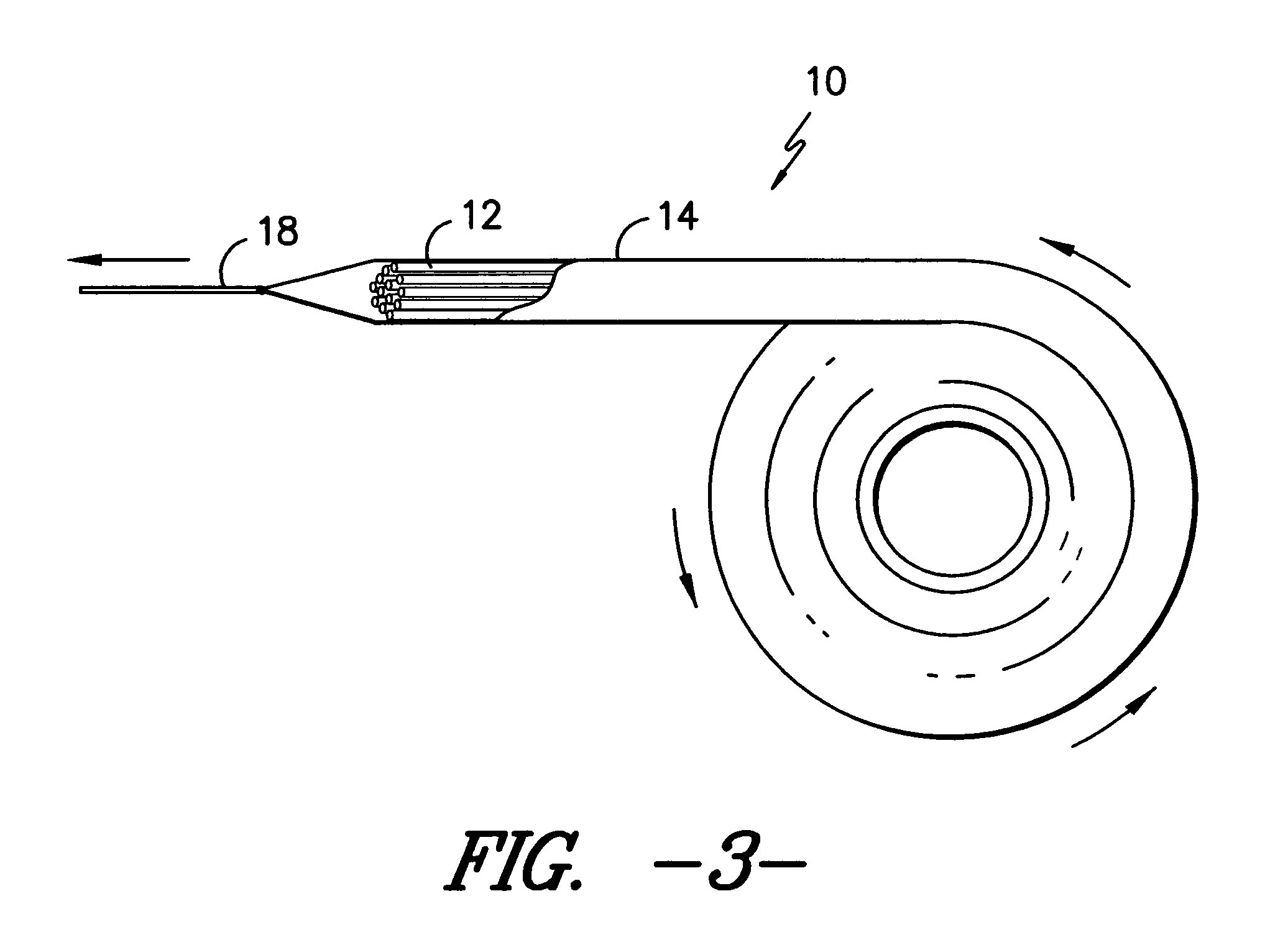
A flexible innerduct guide tube assembly configured to contain a cable within a conduit is provided. The innerduct assembly includes a plurality of guide tubes, each tube configured to contain at least one cable, wherein the tubes are disposed and bundled within a protective textile sleeve. Each guide tube may contain means for pulling a cable into the tube, and such pulling means may include pull cord or tape, or any other means suitable for installing a cable into the guide tube. Other principal features of the invention relate to the material of which the innerduct guide tube assembly is formed, as well as methods for manufacturing and using the innerduct assembly.

Description

BACKGROUND OF THE INVENTION [0001] The present invention generally relates to tubular conduit of the type that might be employed for the housing of cables, either underground or within buildings, such as fiber optic cable, coaxial cable, or the like. More particularly, the present invention relates to a partitioning device, which may be inserted into such a conduit such that the conduit is divided into separate areas. Specifically, the present invention is directed toward an elongated partitioning device which is flexible, such that it may be inserted into a conduit which is already in place, which may already have at least one cable positioned therein, and which may have turns, bends, or the like therein. [0002] Cable, such as fiber optic communication cable, is often provided underground in great lengths, and may even extend for many miles. It is known in the art to bury the cable in the ground so that the area above ground is not cluttered with the cable and its respective suppor...

Claims


Application Information

Patent Timeline
IPC IPC(8): H01R13/60
CPCH02G9/06G02B6/4459D02G3/185G02B6/50H01R13/00
Inventor MORRIS, DAVID DREW
Owner MILLIKEN & CO
Learn More