
Ultrasonic surgical shears and method for sealing a blood vessel using same

Active Publication Date: 2005-09-01
CILAG GMBH INTERNATIONAL
View PDF9 Cites 32 Cited by
  • Summary
  • Abstract
  • Description
  • Claims
  • Application Information

AI Technical Summary

Benefits of technology

[0009] Several benefits and advantages are obtained from one or more of the method and the embodiments of the invention. Exerting an ultrasonic surgical shears coaptation pressure from 60 psi to 210 psi provides for improved blood vessel sealing with shorter transection times on 3 mm or smaller blood vessels than conventionally is possible and provides for blood vessel sealing with acceptable transection times and burst pressures on blood vessels larger than 3 mm, which is not conventionally possible.

Problems solved by technology

However, this is not done because conventional thought is that decreasing the blood-vessel transection time using a higher clamping force will lead to a degradation in coagulation performance (i.e., a lowering of the burst pressure of a sealed end of the transected blood vessel).
Conventional ultrasonic surgical shears are not used on blood vessels larger than 3 mm because the clamping force used is inadequate for proper coaptation.

Method used


Image

  • Ultrasonic surgical shears and method for sealing a blood vessel using same
  • Ultrasonic surgical shears and method for sealing a blood vessel using same
  • Ultrasonic surgical shears and method for sealing a blood vessel using same

Examples


first embodiment

[0024] the invention is for an ultrasonic surgical shears 18 and is shown in FIG. 2. The ultrasonic surgical shears 18 includes an ultrasonic surgical blade 20, a clamping arm 22, and a tissue pad 24. The clamping arm 22 is operable to open and close toward the blade 20. The tissue pad 24 is attached to the clamping arm 22. The ultrasonic surgical shears 18 also includes means 28 for exerting a clamping force on the clamping arm 22 creating a clamping pressure between and including 60 psi and 210 psi on tissue disposed between the tissue pad 24 and the blade 20.

[0025] In one enablement of the first embodiment of FIG. 2, the clamping-force-creating means 28 includes a motor which rotates one of the clamping arm and the blade relative to the other of the clamping arm and the blade, wherein the motor is preselected to cause a known-size clamping surface area to exert the desired pressure on tissue large enough to cover the clamping surface area. In another enablement, the clamping-forc...

second embodiment

[0027] the invention is for an ultrasonic surgical shears 30 and is shown in FIG. 3. The ultrasonic surgical shears 30 includes an ultrasonic surgical blade 32, a clamping arm 34, and a tissue pad 36. The clamping arm 34 is operable to open and close toward the blade 32. The tissue pad 36 is attached to the clamping arm 34. The ultrasonic surgical shears 30 also includes means 40 for limiting a user-applied clamping force on the clamping arm 34 creating a clamping pressure between and including 60 psi and 210 psi on tissue disposed between the tissue pad 36 and the blade 32.

[0028] In one enablement of the second embodiment of FIG. 3, the force-limitation means 40 includes a torque-limiting mechanism as in a conventional torque wrench. Other equivalent enablements are left to the artisan.

[0029] In one application of the second embodiment of FIG. 3, the clamping pressure is between and including 120 psi and 180 psi. In one variation, the clamping pressure is substantially 150 psi. In...


PUM


Abstract

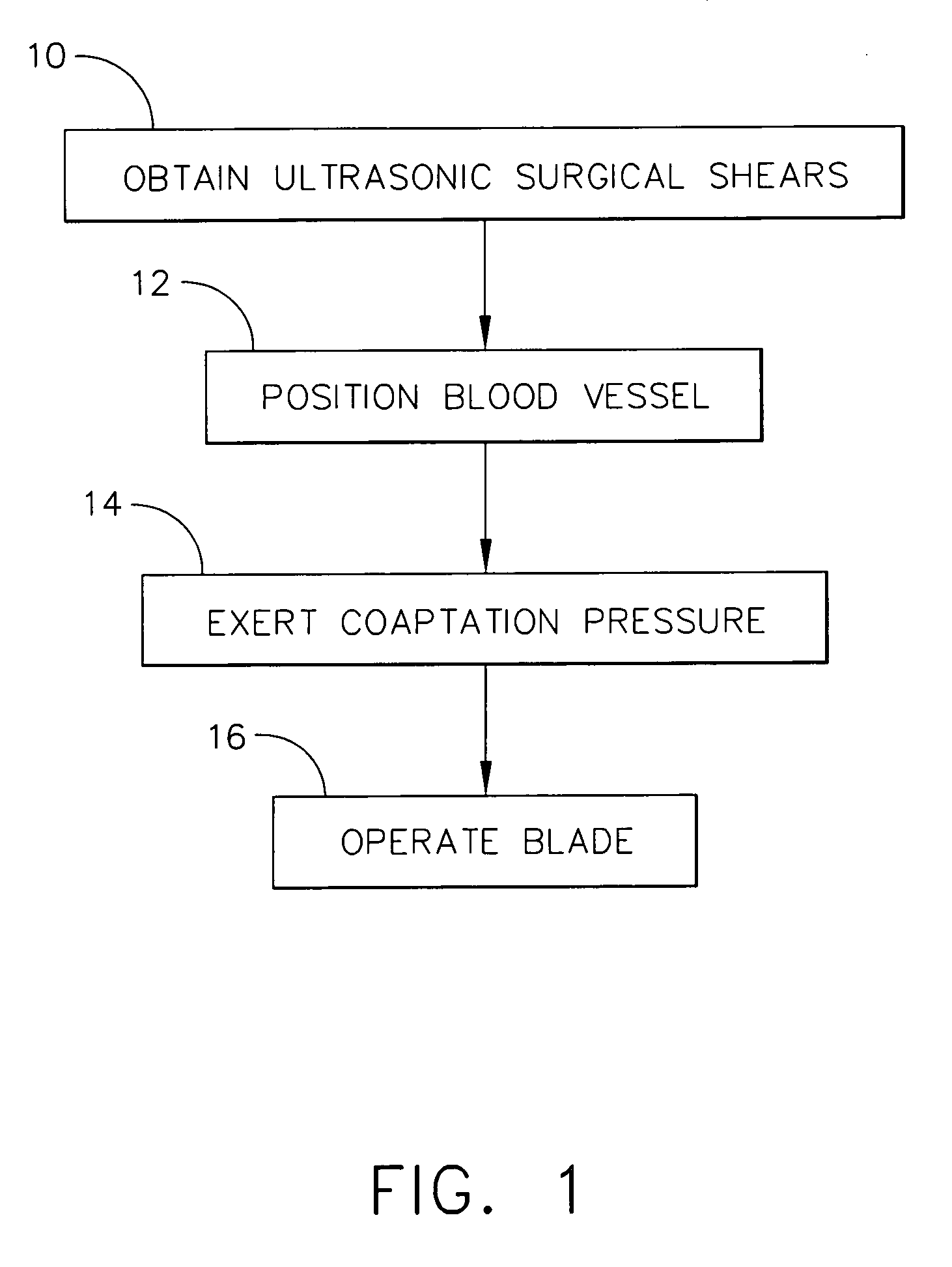
An ultrasonic surgical shears includes an ultrasonic surgical blade, a clamping arm operable to open and close toward the blade, and a tissue pad attached to the clamping arm. A method for sealing a blood vessel of a patient includes obtaining an ultrasonic surgical shears and positioning the blood vessel between the blade and the tissue pad. The clamping arm is operated to exert an average coaptation pressure on the blood vessel between and including 60 psi and 210 psi. The blade is ultrasonically vibrated to transect and seal the blood vessel.

Description

REFERENCE TO RELATED APPLICATIONS [0001] The present application claims the priority benefit of U.S. provisional patent application Ser. No. 60 / 548,308, filed on Feb. 27, 2004, the contents of which are incorporated herein by reference. [0002] This application contains subject matter related to co-owned patent application Ser. No. 10 / 289,787, filed on Nov. 7, 2002, entitled “Ultrasonic Clamp Coagulator Apparatus Having an Improved Clamping End-Effector”, the contents of which is incorporated herein by reference.FIELD OF THE INVENTION [0003] The present invention is related generally to surgical instruments, and more particularly to an ultrasonic surgical shears and to a method for sealing a blood vessel using an ultrasonic surgical shears. BACKGROUND OF THE INVENTION [0004] Ultrasonic surgical instruments are known which include ultrasonic surgical shears having an ultrasonic surgical blade, a clamping arm operable to open and close toward the blade, a tissue pad attached to the cla...

Claims


Application Information

Patent Timeline
IPC IPC(8): A61B17/12A61B17/28A61B17/32
CPCA61B17/12A61B2017/2825A61B17/320092A61B2017/320094A61B2017/320093A61B2017/320095
Inventor HOUSER, KEVIN L.NOSCHANG, SARAH A.
Owner CILAG GMBH INTERNATIONAL
Learn More