
Rotating car seat mechanism

a car seat and mechanism technology, applied in the direction of movable seats, chairs, sofas, etc., can solve the problems of affecting the safety of passengers, the inability of a disabled body to board a car, and the strength of the structure, so as to achieve the effect of convenient and convenient installation, simple structure, and convenient control

Active Publication Date: 2005-08-18
PRO GLORY ENTERPRISES
View PDF18 Cites 12 Cited by
  • Summary
  • Abstract
  • Description
  • Claims
  • Application Information

AI Technical Summary

Benefits of technology

[0013] A primary objective of the present invention is to provide a simple, stable, easy control, smaller space needed and a more concise seat movement out of a car door. Comprising of a sliding plate, a rotating plate, a rotating axis, a cylindrical pivot rod secured to a base frame and a guiding socket plate assembled to the rotating plate. The pivoting rod is inserted into a guiding socket on the guiding socket board, allowing the seat to safely and securely exceed the car door by firstly rotating to a specific angle and simultaneously rotating and sliding forward thereafter. The rotating car seat mechanism is installed to an upper side of the sliding plate and inherits the flat forward and backward movement of a conventional car seat.

Problems solved by technology

As a space where a seat is installed in a conventional car is small and there is a gap between the ground and the floorboard of a car, it is difficult for a disabled body to board a car, therefore there is a need for installation of equipment that may assist handicapped passengers to enter and exit a vehicle.
The two aforesaid car seat rotating structure needs a large space for installation, and is more difficult to be installed into a narrow space of a small car.
Although the space that is needed by the aforesaid mechanism is smaller, a stronger structure is needed, therefore more costly, and more complex to install.
The space needed is smaller than that of a secured-type rotating axis, and because the length of the linking rods are fixed, therefore the rotation of the car seat becomes fixed correspondingly and different space limitations of various cars, which results in reduced flexibility of the mechanism.
In conclusion, the aforementioned various patent designs, the rotating car seat of the secured-type rotating axis need larger spaces for installation, not suitable for installing in narrow spaces of the front seat of a small vehicles.
Yet, the mechanism is more complex and the rotating car seat lacks flexibility.

Method used


Image

  • Rotating car seat mechanism
  • Rotating car seat mechanism
  • Rotating car seat mechanism

Examples


Embodiment Construction

[0025] To better understand the present invention, detailed descriptions shall be given with the accompany drawings hereunder.

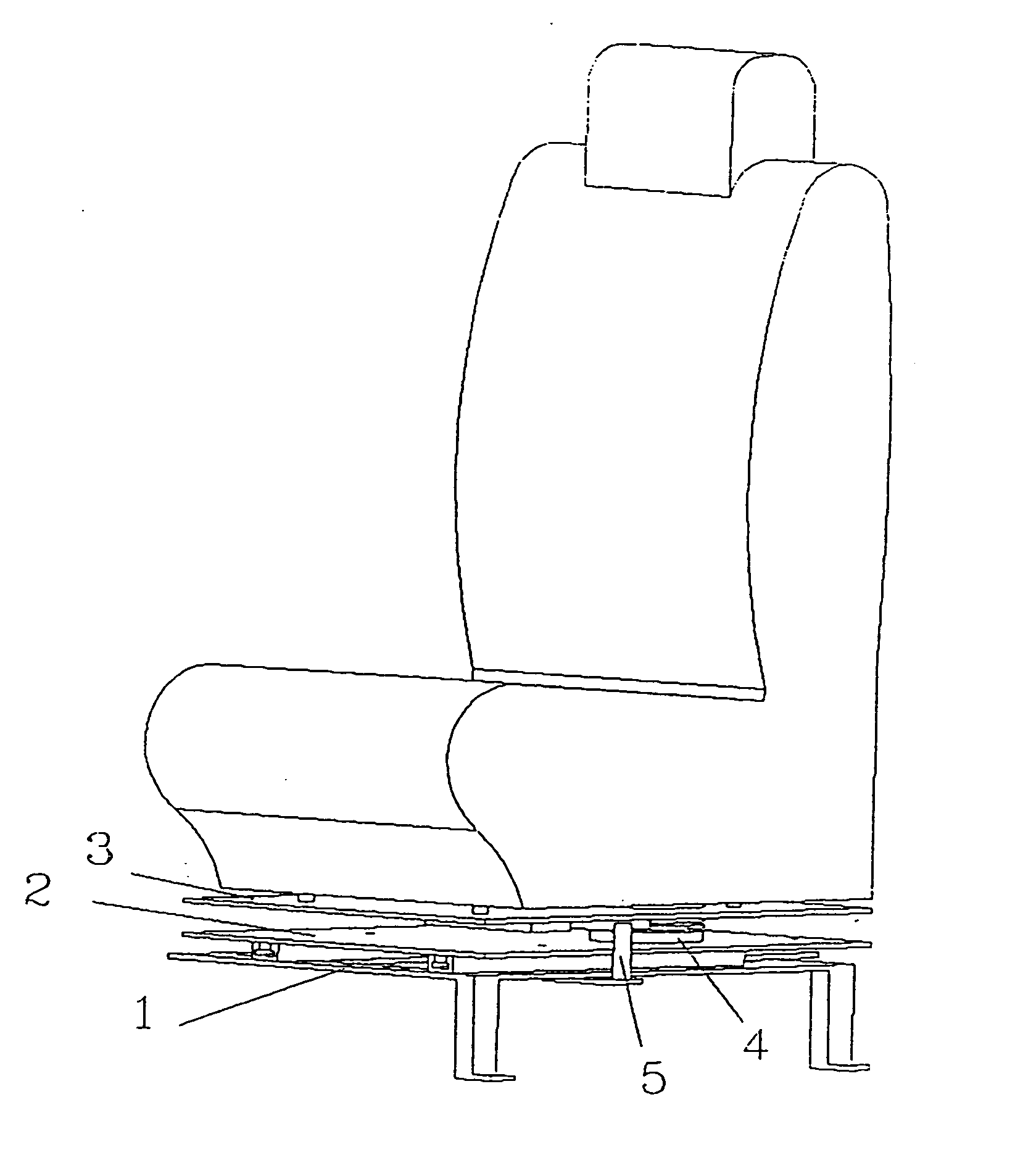
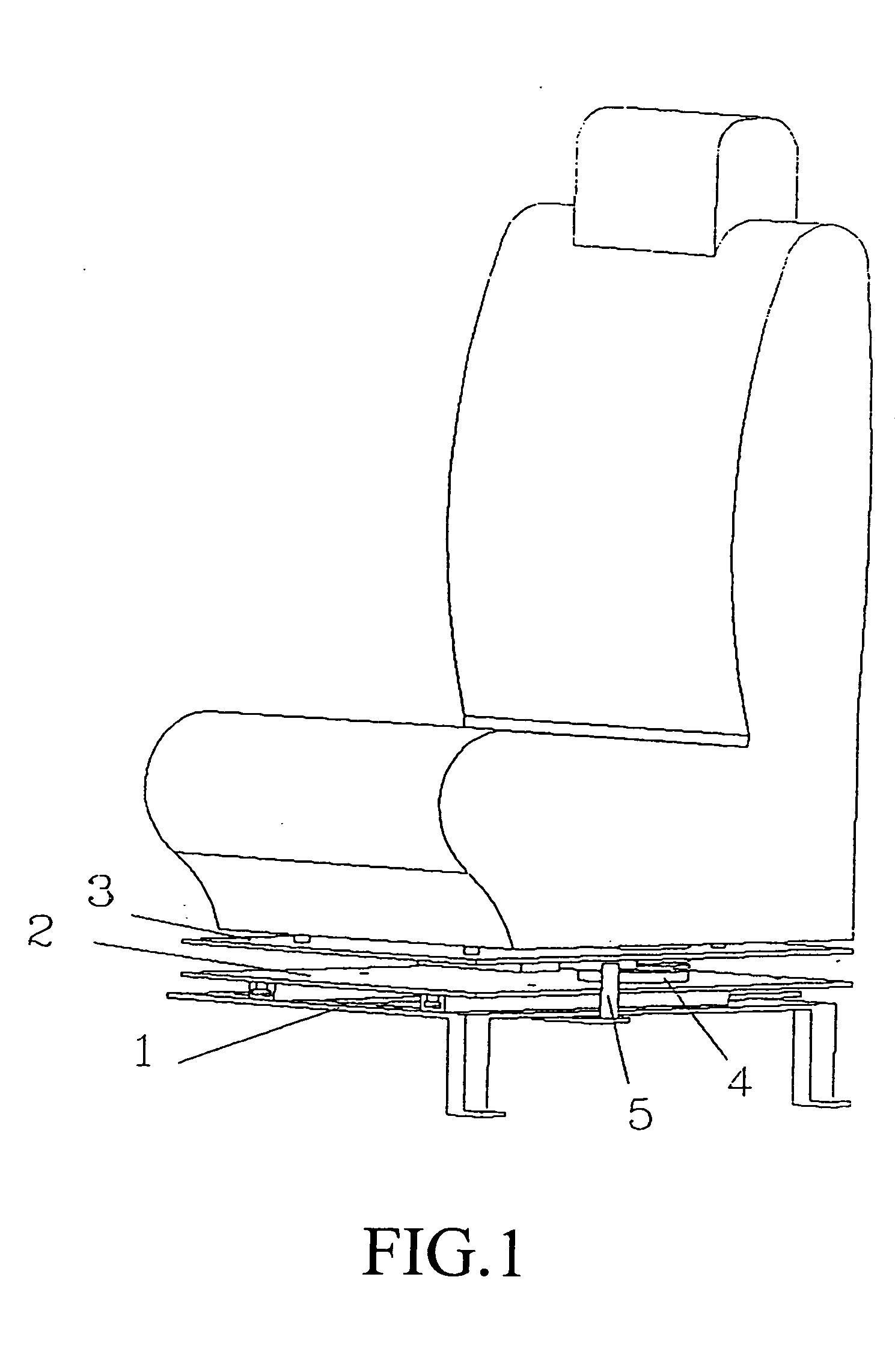
[0026] As shown in FIG. 1 a rotating car seat mainly comprises of a base seat 1, a sliding plate 2, a rotating plate 3, a rotating axis 4 and a cylindrical pivoting rod 5, whereas FIG. 2 shows the assembly of the respective components thereafter.

[0027] As shown in FIG. 3, the base seat 1 comprises of a base frame 11 and a sliding track 12, wherein four securing apertures 111 are formed on the base frame 11, thereby securing the base frame 11 to a floorboard of a car by means of screws.

[0028] As shown in FIG. 4, four sliding track securing apertures 21 and a rotating axis securing aperture 22 is formed on the sliding plate 2, thereby securing the sliding plate 2 to the sliding track 12 of the base seat 1 by means of screws.

[0029] As shown in FIG. 5, a plurality of guiding socket plate securing apertures 33, four seat securing apertures 34 and a rotating ax...


PUM


Abstract

A rotating car seat mechanism includes a base seat, a sliding plate, a rotating plate, a guiding socket plate, a rotating axis and a cylindrical pivot rod. The sliding plate is placed inside a car, allowing an upper end of the cylindrical pivot rod to be positioned at the exit of the guiding socket, further enabling the rotation out of the car door and sliding the cylindrical pivot rod into the guiding socket. Due to the designated dotted centric line as illustrated by the guiding socket customizing the movement of the cylindrical pivot rod, the rotating plate not only rotates on the rotating axis, but also drives the rotating axis forward. After applying a suitable degree of motion, the rotating plate exceeds out of a narrow space of he car, whereas, an opposite amount of motion enables the rotating plate to return to the original point.

Description

BACKGROUND OF THE INVENTION [0001] (a) Field of the Invention [0002] The present invention relates to a rotating car seat designed for the handicapped, more particularly, to aid disadvantaged passengers in entering and exiting a vehicle, further provides comfortable seating and reduces the size of a special rotating mechanism. [0003] (b) Description of the Prior Art [0004] The government has cleared many spaces to patronize the elderly and the handicapped, allowing disabled bodies to use a number of public facilities. As a space where a seat is installed in a conventional car is small and there is a gap between the ground and the floorboard of a car, it is difficult for a disabled body to board a car, therefore there is a need for installation of equipment that may assist handicapped passengers to enter and exit a vehicle. [0005] Referring to a Taiwanese patent, publication number 338022, titled A Conventional Rotating Car Seat relates to a type of rotating mechanism of a car seat, ...

Claims


Application Information

Patent Timeline
Patent Type & Authority Applications(United States)
IPC IPC(8): A47C3/18A47C7/50B60N2/14F16M11/08
CPCB60N2/14A47C3/18B60N2/245
Inventor CHUNG, TIEN-TUNGSHEN, HSIU-CHU
Owner PRO GLORY ENTERPRISES
Learn More