
Permanently installed in-well fiber optic accelerometer-based seismic sensing apparatus and associated method

a fiber optic accelerometer and seismic sensing technology, applied in the field of permanent installation of in-well fiber optic accelerometer-based seismic sensing apparatus, can solve the problems of unsuitable deeper deployment, unsuitable for seismic readings that cannot be taken periodically, and require well intervention

Inactive Publication Date: 2005-08-11
WEATHERFORD TECH HLDG LLC
View PDF12 Cites 63 Cited by
  • Summary
  • Abstract
  • Description
  • Claims
  • Application Information

AI Technical Summary

Problems solved by technology

While seismic data can be actively or passively gathered using wireline-deployed geophones or hydrophones, seismic readings can only be taken periodically and require well intervention, perhaps requiring the cessation of fluid flow (i.e., production or injection) in the well.
Moreover, while permanent geophone arrays have been deployed in relatively shallow wells, they are unsuitable for deeper deployments because their complexity and associated electronics cannot withstand the high temperatures and pressures encountered downhole for long periods of time.

Method used


Image

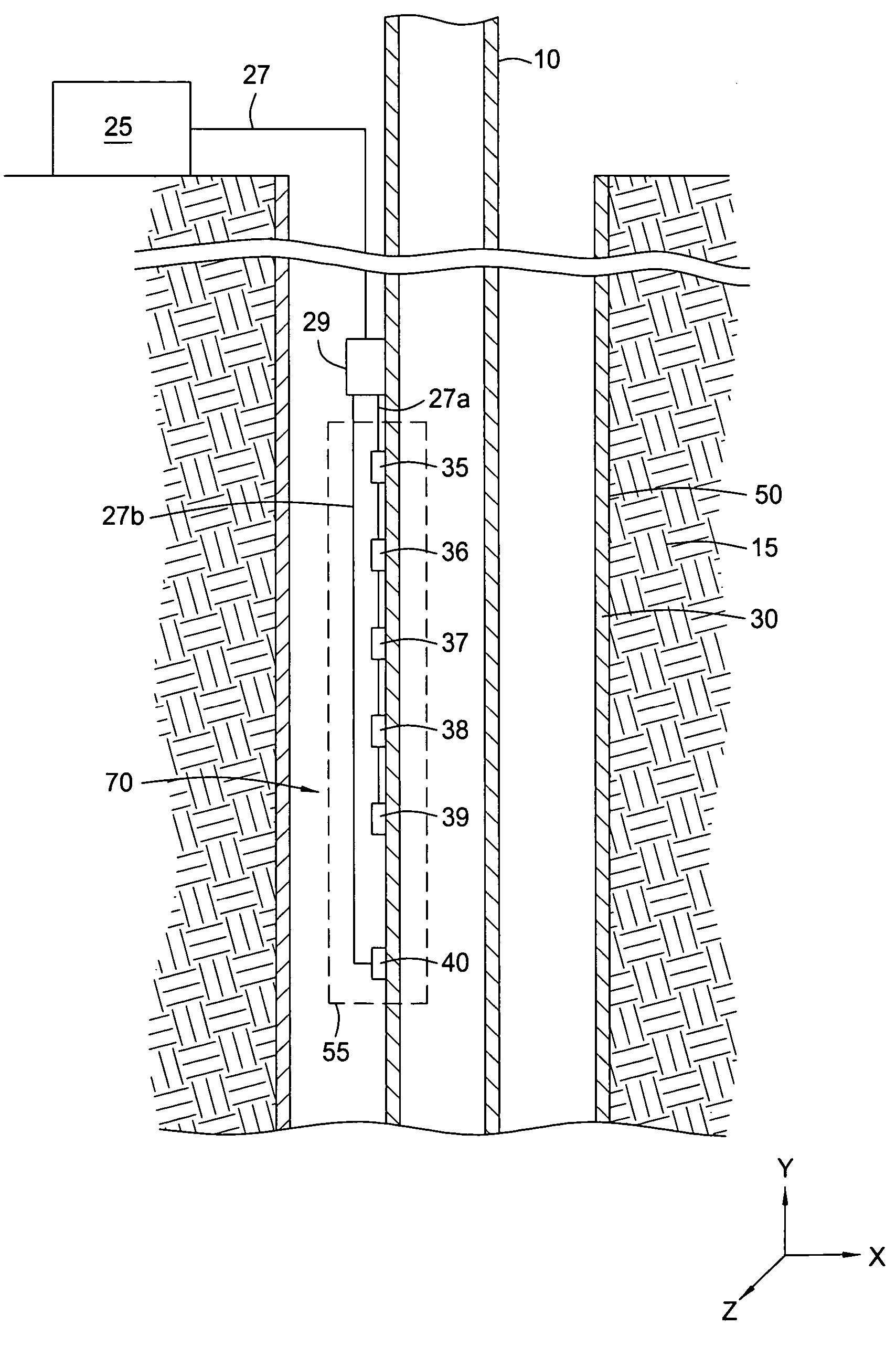
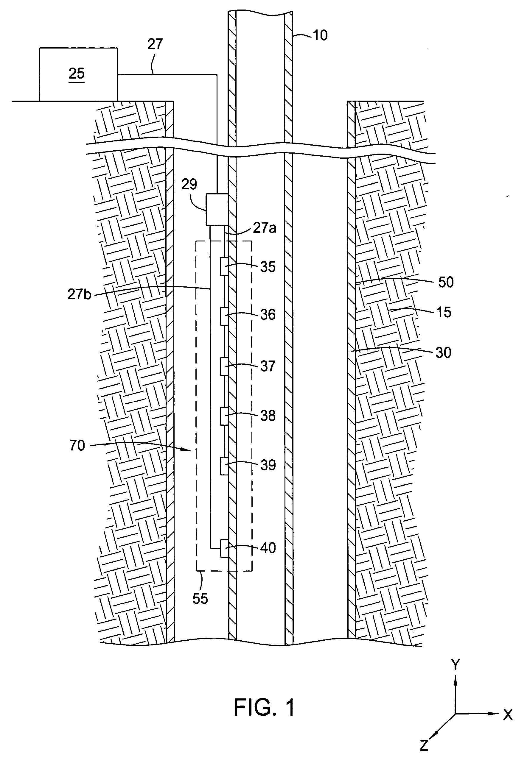
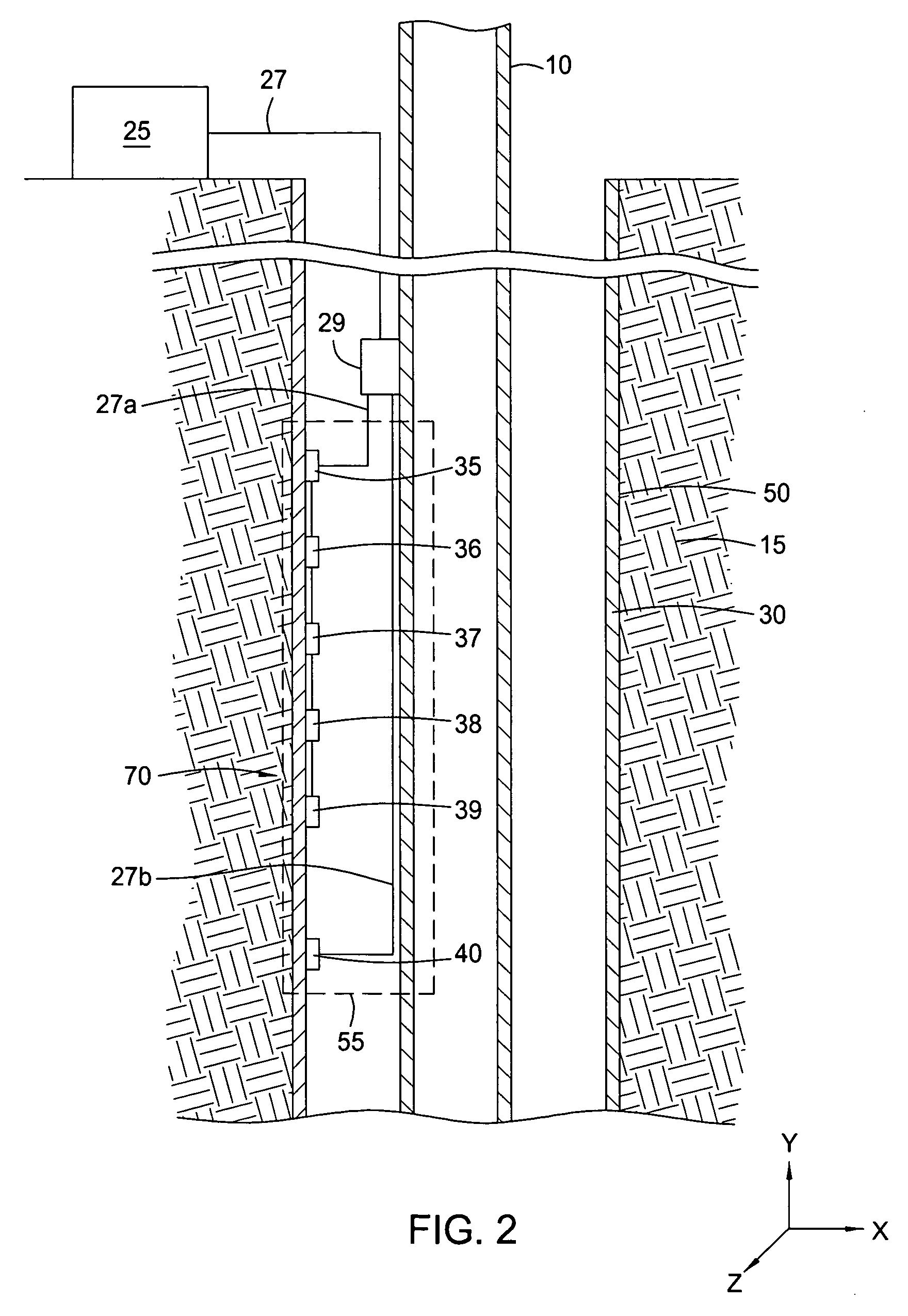
  • Permanently installed in-well fiber optic accelerometer-based seismic sensing apparatus and associated method
  • Permanently installed in-well fiber optic accelerometer-based seismic sensing apparatus and associated method
  • Permanently installed in-well fiber optic accelerometer-based seismic sensing apparatus and associated method

Examples


Embodiment Construction

[0019] Embodiments of the present invention include an optical seismic sensing system for gathering both active and passive seismic data that can be installed permanently in-well to collect seismic data and / or fluid movement data on demand. Embodiments of the present invention provide a multi-channel, multi-component, fiber optic seismic sensing system for in-well applications.

[0020] Embodiments of a downhole seismic sensor system using optical sensing technology (e.g., optical fibers) of the present invention provide improved information about fluid migration on a permanent basis without the need for periodic well intervention and without the use of less reliable downhole electronic devices.

[0021] The following references are all incorporated herein by reference in their entireties: F. Bostick “Field Experimental Results of Three-Component Fiber-Optic Sensors,” 70th Annual International Mtg., Society of Exploration Geophysicists, August 2000; D. Gysling & F. Bostick, “Changing Pa...


PUM


Abstract

Embodiments of the present invention include a fiber optic seismic sensing system for permanent downhole installation. In one aspect, the present invention includes a multi-station, multi-component system for conducting seismic reservoir imaging and monitoring in a well. Permanent seismic surveys may be conducted with embodiments of the present invention, including time-lapse (4D) vertical seismic profiling (VSP) and extended micro-seismic monitoring. Embodiments of the present invention provide the ability to map fluid contacts in the reservoir using 4D VSP and to correlate micro-seismic events to gas injection and production activity.

Description

CROSS-REFERENCE TO RELATED APPLICATIONS [0001] This application claims benefit of U.S. Provisional Patent Application Ser. No. 60 / 454,839, filed Mar. 14, 2003, which is herein incorporated by reference in its entirety.BACKGROUND OF THE INVENTION [0002] 1. Field of the Invention [0003] Embodiments of the present invention are directed to apparatus and methods for in-well seismic sensing using fiber optic accelerometers. Embodiments of the present invention also are directed to apparatus and methods for in-well seismic sensing using optical hydrophones. [0004] 2. Description of the Related Art [0005] Installing permanent seismic sensors in a wellbore to detect the movement of fluids over time in a surrounding reservoir would represent a significant advance in reservoir management, and is considered by many as a key element for instrumented oilfields. As companies focus more on maximizing recovery in existing and future fields, improved production and reservoir management is becoming i...

Claims


Application Information

Patent Timeline
Patent Type & Authority Applications(United States)
IPC IPC(8): E21B47/00E21B47/01E21B47/12G01H9/00G01V1/00G01V1/40
CPCE21B47/011G01V1/40G01H9/004E21B47/123E21B47/017E21B47/135
Inventor BOSTICK, FRANCIS X. III
Owner WEATHERFORD TECH HLDG LLC
Learn More