
System for improving an image displayed on a display

a technology for improving the display and image, applied in the field of display images, can solve the problems of loss of luminance resolution at the subpixel sampling rate, mis-registration of color fields, and aforementioned techniques that do not take advantage of potential display resolution

Inactive Publication Date: 2005-08-04
SHARP KK
View PDF21 Cites 96 Cited by
  • Summary
  • Abstract
  • Description
  • Claims
  • Application Information

AI Technical Summary

Problems solved by technology

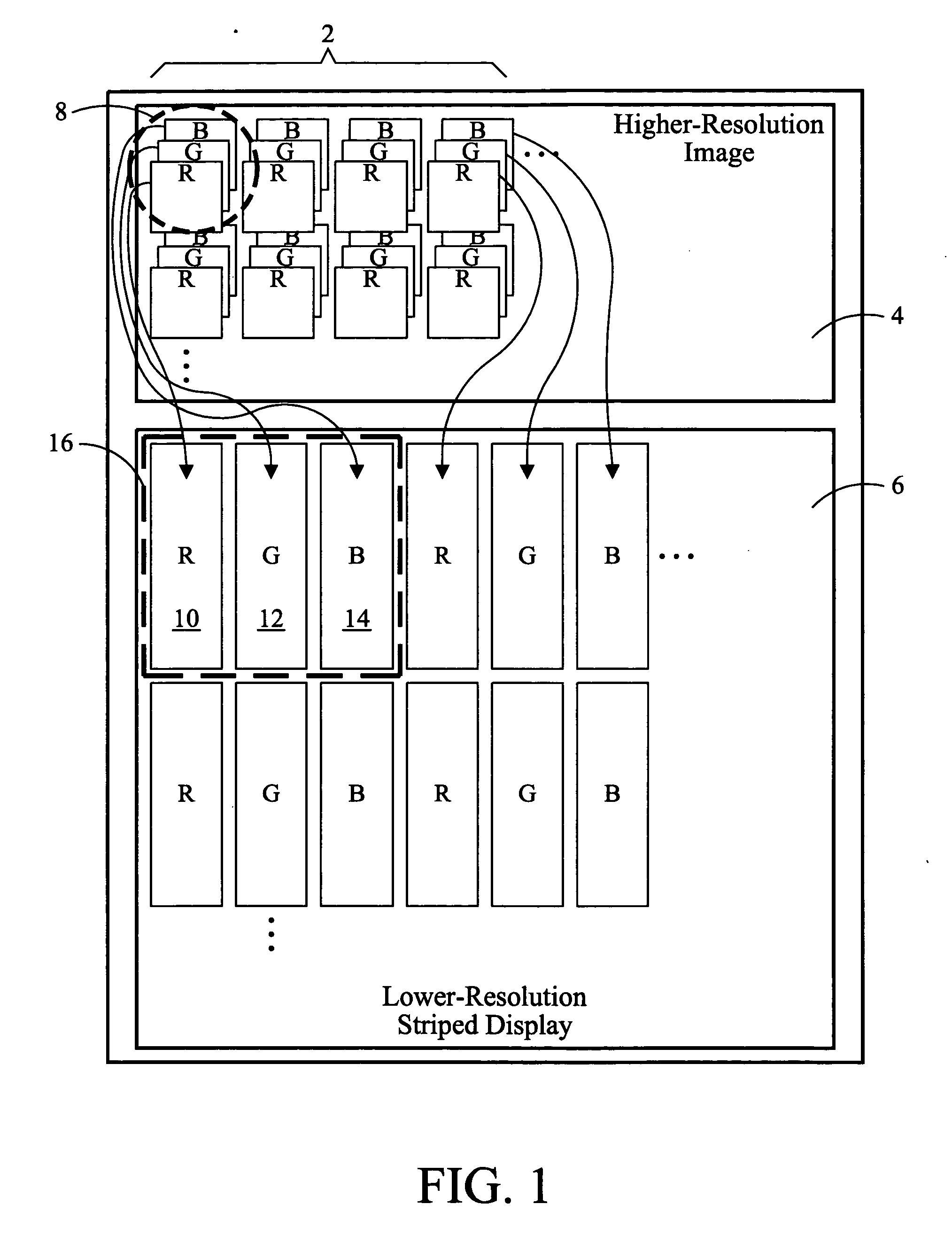
Because the display device does not allow overlapping color elements the subpixels are spatially distinct.
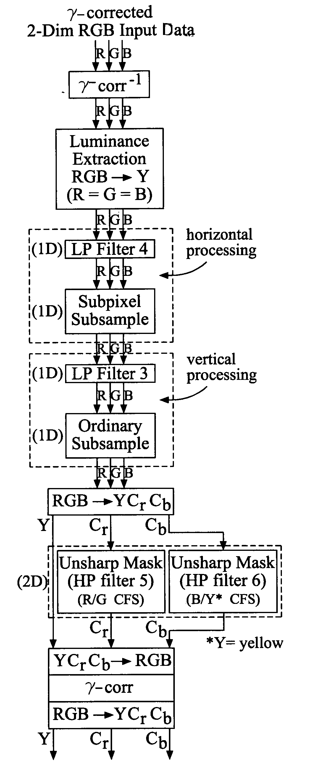
In the case that prefiltering is omitted, the subsampling process would cause undesirable aliasing artifacts, and, accordingly, various methods are used, such as averaging the neighboring un-sampled pixels in with the sampled pixel, to reduce the aliasing.
In addition, the subsampling technique of FIG. 1 results in mis-registration of the color fields each of which carries a portion of the luminance information.
This is due to the displaced subpixels, and leads to a loss of luminance resolution attainable at the subpixel sampling rate.
It has been realized that the aforementioned techniques do not take advantage of potential display resolution beyond that determined by the Nyquist limit due to the display pixel spacing.
Unfortunately, this “naïve” method of subpixel subsampling produces color artifacts (a.k.a., “color aliasing” or “chrominance aliasing”) in addition to the beneficial enhanced luminance resolution.
It may be observed that viewers can not effectively see high frequency color content.

Method used


Image

  • System for improving an image displayed on a display
  • System for improving an image displayed on a display
  • System for improving an image displayed on a display

Examples


Embodiment Construction

[0033] An achromatic image, may be defined as an image having no readily visible color variation. This achromatic condition may occur when an image contains identical multiple layers or color channels thereby yielding a gray-scale image. Also, an achromatic image occurs when the subpixels have the same common value.

[0034] Embodiments may be described with reference to “RGB” images or domains, or “additive color domains”, or “additive color images.” These terms refer to any form of multiple component image domain with integrated luminance and chrominance information, including, but not limited to, RGB domains. Embodiments may also be described with reference to “YCbCr” images or domains, “opponent color” domains or images, or “color difference” domains or images. These terms refer to any form of multiple component image domain with channels which comprise distinct luminance channels and chrominance channels including, but not limited to, YCbCr, LAB, YUV, and YIQ domains.

[0035] The ...


PUM


Abstract

A system for improving the an image displayed on a display.

Description

BACKGROUND OF THE INVENTION [0001] The present invention relates to displaying images on a display. [0002] The most commonly used method for displaying high-resolution images on a lower resolution color mosaic (i.e. color matrix) display is to prefilter and re-sample the pixels 2 of the high-resolution image 4 down to the resolution of the low-resolution display 6, as shown in FIG. 1. In the process, the R, G, B values of selected color pixels 8 are mapped to the separate R, G, B elements 10, 12 and 14 of each display pixel 16. These R, G, B elements 10, 12 and 14 of a display pixel are sometimes also referred to as subpixels. Because the display device does not allow overlapping color elements the subpixels are spatially distinct. In addition, the subpixels can only take on one of the three R, G, or B colors. The color's amplitude, however, can be varied throughout the entire grey scale (i.e. brightness) range (e.g., 0-255 for “8-bit” pixels). The subpixels often have approximately...

Claims


Application Information

Patent Timeline
IPC IPC(8): G06K9/40G06T3/40G09G3/20
CPCG06T3/4015G09G2340/0457G09G2300/0452G09G3/2003
Inventor MESSING, DEANKEROFSKY, LOUIS J.
Owner SHARP KK
Learn More