
Hose connector

Inactive Publication Date: 2005-08-04
CERTAINTEED CORP
View PDF16 Cites 1 Cited by
  • Summary
  • Abstract
  • Description
  • Claims
  • Application Information

AI Technical Summary

Benefits of technology

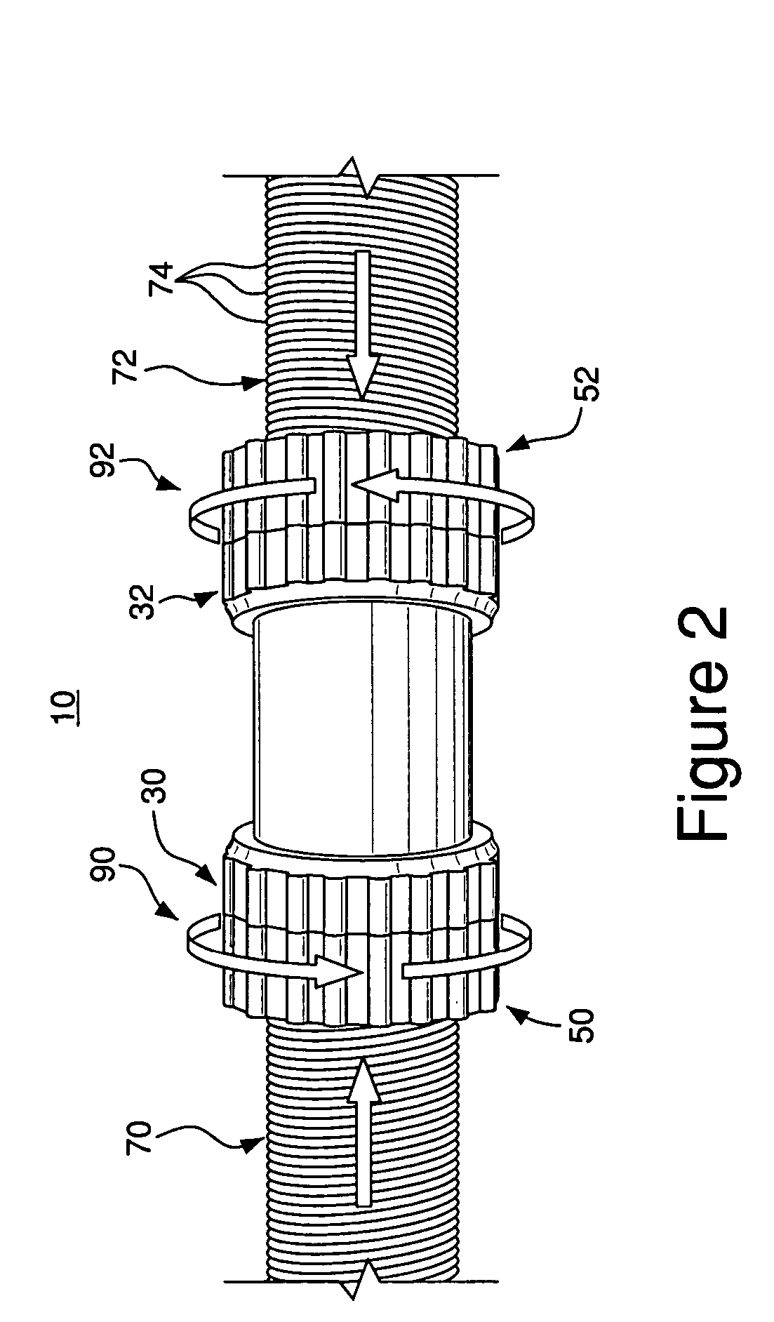
[0008] The hose connector and method as described herein may advantageously be used to connect hoses, such as loose fill insulation hoses. Unlike current connectors that are time consuming, unyielding and require tools to employ, the present connector allows for rotation of the hoses, does not require the use of tools to use, and provides for quick assembly and disassembly of the hoses.

Problems solved by technology

The use of such tubes and clamps is time consuming and requires a screw driver to secure the hoses, and are also subject to corrosion and deformation, and tend to cause the hoses to wear prematurely adjacent the clamp.
Further, the use of such tubes and clamps does not allow for the rotation of the hoses relative to the connector once the clamps are tightened.
Such a coupling does not allow for rotation of the hoses.

Method used


Image

  • Hose connector
  • Hose connector
  • Hose connector

Examples


Embodiment Construction

[0018] This description of the exemplary embodiments is intended to be read in connection with the accompanying drawings, which are to be considered part of the entire written description. In the description, relative terms such as “lower,”“upper,”“horizontal,”“vertical,”“above,”“below,”“up,”“down,”“top” and “bottom” as well as derivatives thereof (e.g., “horizontally,”“downwardly,”“upwardly,” etc.) should be construed to refer to the orientation as then described or as shown in the drawing under discussion. These relative terms are for convenience of description and do not require that the apparatus be constructed or operated in a particular orientation. Terms concerning attachments, coupling and the like, such as “connected” and “interconnected,” refer to a relationship wherein structures are secured or attached to one another either directly or indirectly through intervening structures, as well as both movable or rigid attachments or relationships, unless expressly described othe...


PUM


Abstract

A hose connector includes a cylindrical elongated member having a first and second end, a first and second inner sleeve rotatably mounted on the cylindrical member, and a first and second outer sleeve capable of connecting to the respective first and second inner sleeves.

Description

FIELD OF THE INVENTION [0001] The present invention relates to hose connectors, and more particularly to hose connectors for connecting and disconnecting hoses for applying loosefill insulation. BACKGROUND OF THE INVENTION [0002] Insulation may be dispensed in a variety of ways. Generally, a hose is used to dispense the loosefill insulation. The operator positions a hose nozzle in a desired direction and dispenses the insulation from the loosefill source into the area at which the nozzle is aimed. Transporting the loosefill insulation from the source of loosefill into an area, such as an attic or basement, often requires the use of more than a single hose. Hose connectors are employed to connect and extend the hosing to reach longer distances. Typically, these hose connectors are 6″ long steel tubes. The hoses fit over the ends of these tubes and are secured to the tube by screw-type metal hose clamps. The use of such tubes and clamps is time consuming and requires a screw driver to...

Claims


Application Information

Patent Timeline
IPC IPC(8): F16L17/00F16L25/00
CPCF16L25/0036Y10S285/903
Inventor SUDA, MICHAEL D.SACKS, JEFFREYLAIDLEY, CHRISTOPHER
Owner CERTAINTEED CORP
Learn More