
Window and window frame structure thereof

a technology of window frame and window frame, which is applied in the direction of revolving doors, building components, construction, etc., can solve the problems of difficult opening or closing the window, the window frame is left as it is or is removed,

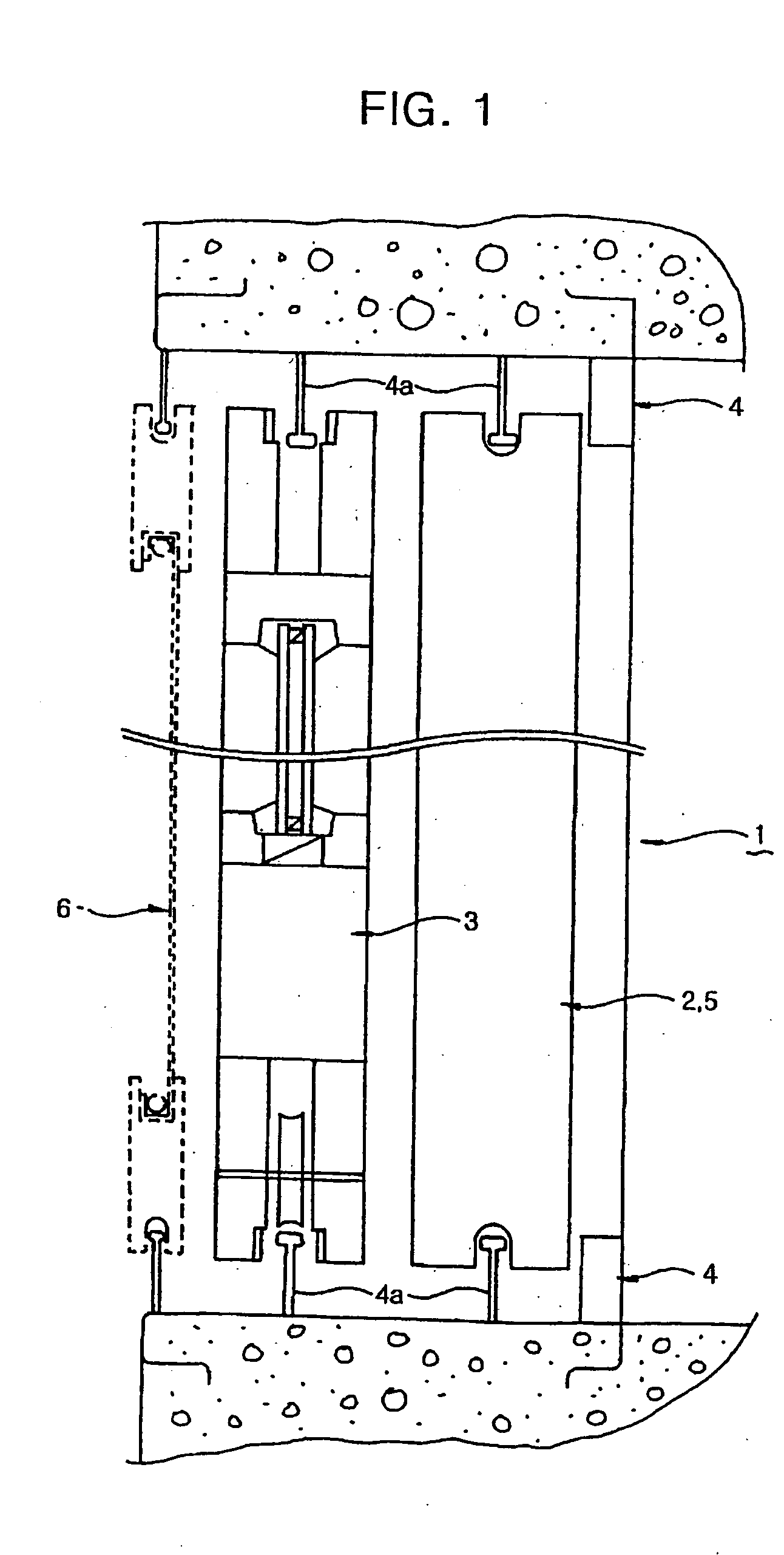
Inactive Publication Date: 2005-07-28
SONG CHI HO
View PDF24 Cites 7 Cited by
  • Summary
  • Abstract
  • Description
  • Claims
  • Application Information

AI Technical Summary

Benefits of technology

[0011] Therefore, an object of the present invention is to solve the problems involved in the prior art, and to provide a structure of a window frame capable of easily enabling efficient use of a veranda space faced to a living room or room by removing an interior window and an exterior window only.
[0012] Another object of the present invention is to prevent dust from being collected in a recessed portion of a guide rail, in the case of a living-room window or ventilation window
[0013] Still another object of the present invention is to prevent the possible falling over a stepped portion by eliminating the stepped portion.
[0014] Further another object of the invention is to easily open and close a window, in the case of presenting a slight eccentricity between interior and exterior windows and sliding recesses of window frames,

Problems solved by technology

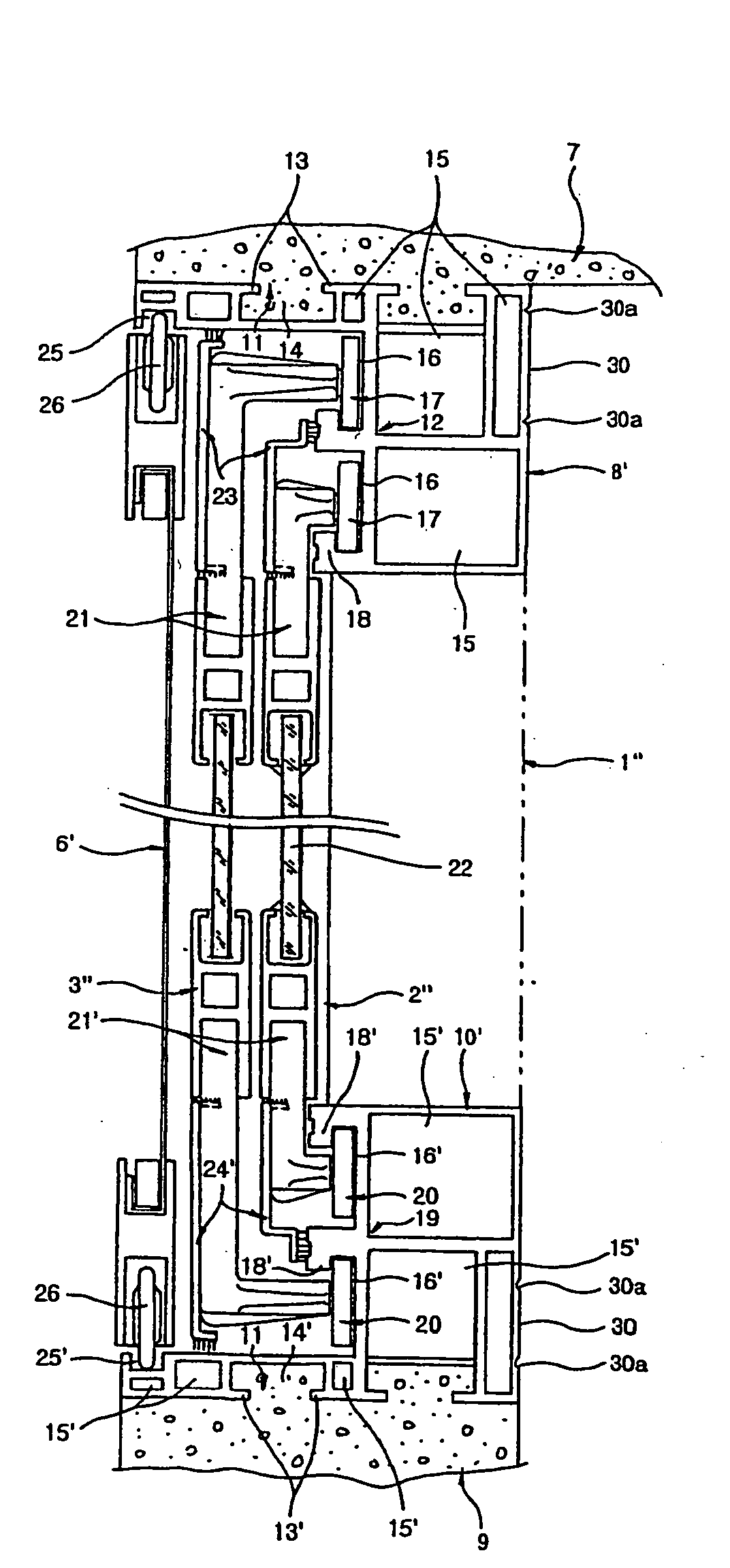
However, since the respective guide rails disposed at the ceiling-side supporting portion of the window frame and the floor-side supporting portion of the window frame which support the interior and exterior windows and the repellent window are vertically protruded from the ceiling and the floor, there is a drawback in that the window frames are left as it is or are removed when constructing the veranda to utilize the veranda space.
Accordingly, even if there is a slight eccentricity between the interior and exterior windows and the guide rail when sliding along the curved window frames, it is difficult to open or close the window.

Method used


Image

  • Window and window frame structure thereof
  • Window and window frame structure thereof
  • Window and window frame structure thereof

Examples


Embodiment Construction

[0023] Reference will now be made in detail to the preferred embodiments of the present invention; examples of which are illustrated in the accompanying drawings.

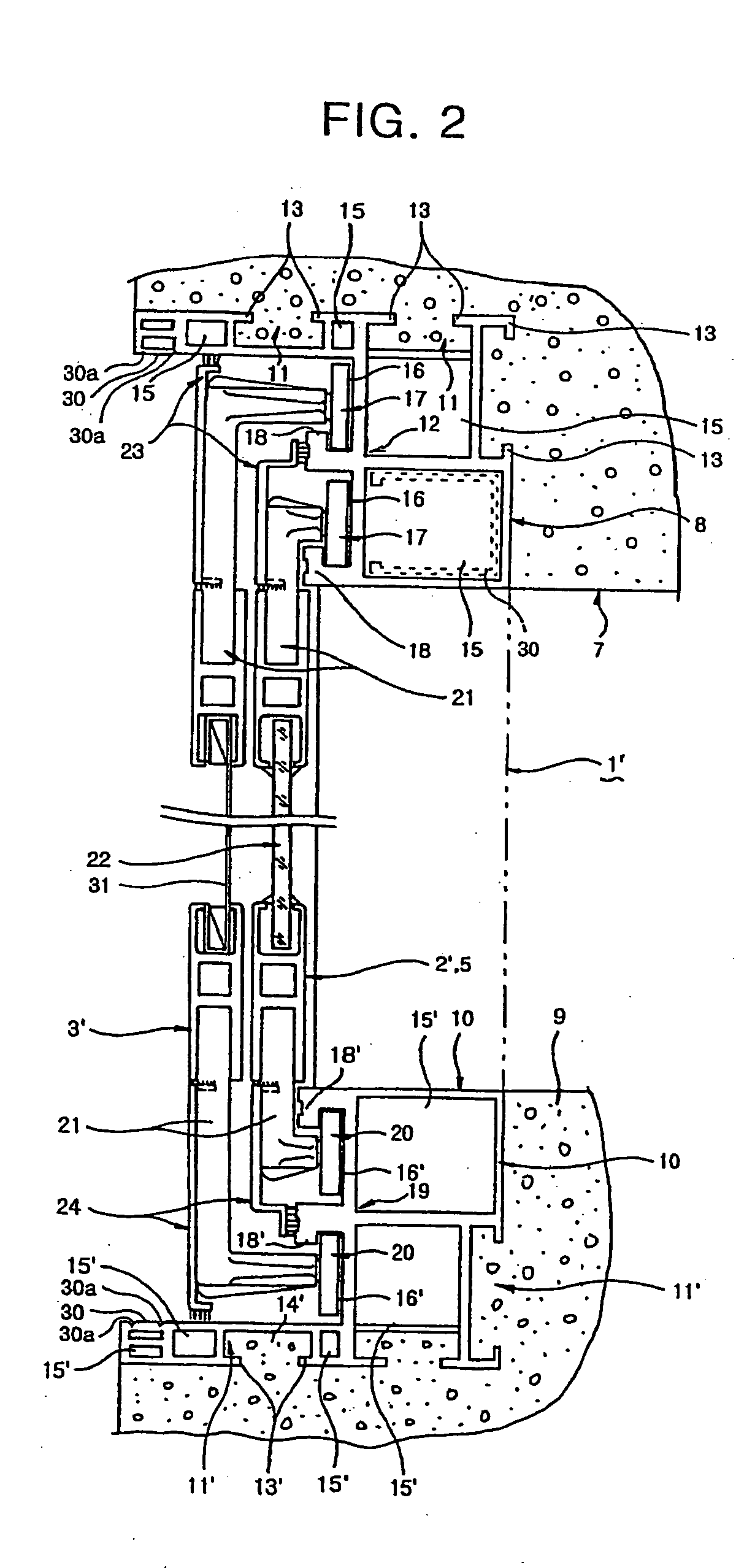
[0024]FIG. 2 is a schematic cross-sectional view illustrating the structure of a window frame for a living-room according to one preferred embodiment of the present invention.

[0025] The structure of the window frame for living-room window according to the present invention includes, as shown in FIG. 2, an upper window frame 8 having at least one recess portion fixedly secured to a concrete casting surface of a ceiling 7, a lower window frame 9 having at least one recess portion secured fixed to a concrete casting surface of a floor to be flush with the concrete casting surface of the floor, an interior window 2′ having both ends inserted into the upper and lower window frames to form a “”-shaped cross section, and an exterior window 3′ arranged apart from the interior window at predetermined intervals and having both ends...


PUM


Abstract

Disclosed is a structure of a window frame used in apartments, detached dwellings, apartment units in a private house, residential / commercial combined buildings, or the like. The structure comprises an upper window frame (8) having at least one recess portion fixedly secured to a concrete casting surface of a ceiling (7), a lower window frame (9) having at least one recess portion secured fixed to a concrete casting surface of floor to be flush with the concrete casting surface of the floor, an interior window (2′) having both ends inserted into the upper and lower window frames to form a “”-shaped cross section, and an exterior window (3′) arranged apart from the interior window at predetermined intervals and having both ends inserted into the upper and lower window frames to form a “”-shaped cross section.

Description

TECHNICAL FIELD [0001] The present invention relates to a window frame structure for use in apartments, detached dwellings, apartment units in a private house, residential / commercial combined buildings, or the like, and more particularly, to a structure of a window frame capable of easily enlarging a veranda space as a living room or a room according to the convenience of residents. BACKGROUND ART [0002] Recently, residents or appointed tenants enlarge a space of a living room or a room so far as a veranda to more effectively utilize the space, if necessary. [0003]FIG. 1 is a schematic cross-sectional view illustrating the structure of a conventional window frame for a living-room. [0004] Conventional living-room window or ventilation window 1 includes, as shown in FIG. 1, an interior window 2 and an exterior window 3, the interior and exterior windows slidingly moved along a window frame 4. The window frame 4 consists of one support frame secured to a ceiling, a floor and both wall...

Claims


Application Information

Patent Timeline
Patent Type & Authority Applications(United States)
IPC IPC(8): E06B3/32E06B3/46E06B3/70E06B3/90
CPCE06B3/4609E06B3/903E06B3/7007E06B3/32
Inventor SONG, CHI HO
Owner SONG CHI HO
Learn More