Eureka AIR delivers breakthrough ideas for toughest innovation challenges, trusted by R&D personnel around the world.

Air conditioning apparatus with blower and electric heater in common housing

Active Publication Date: 2005-07-07
ADVANCED DISTRIBUTOR PRODS
View PDF1 Cites 8 Cited by
  • Summary
  • Abstract
  • Description
  • Claims
  • Application Information

AI Technical Summary

Benefits of technology

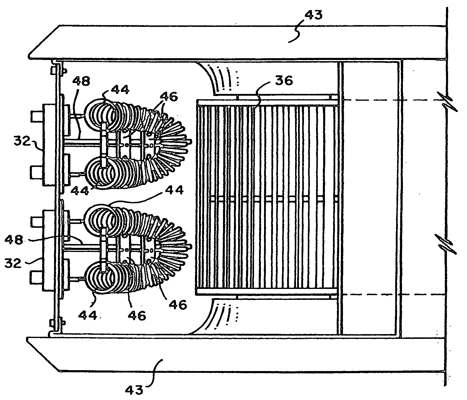
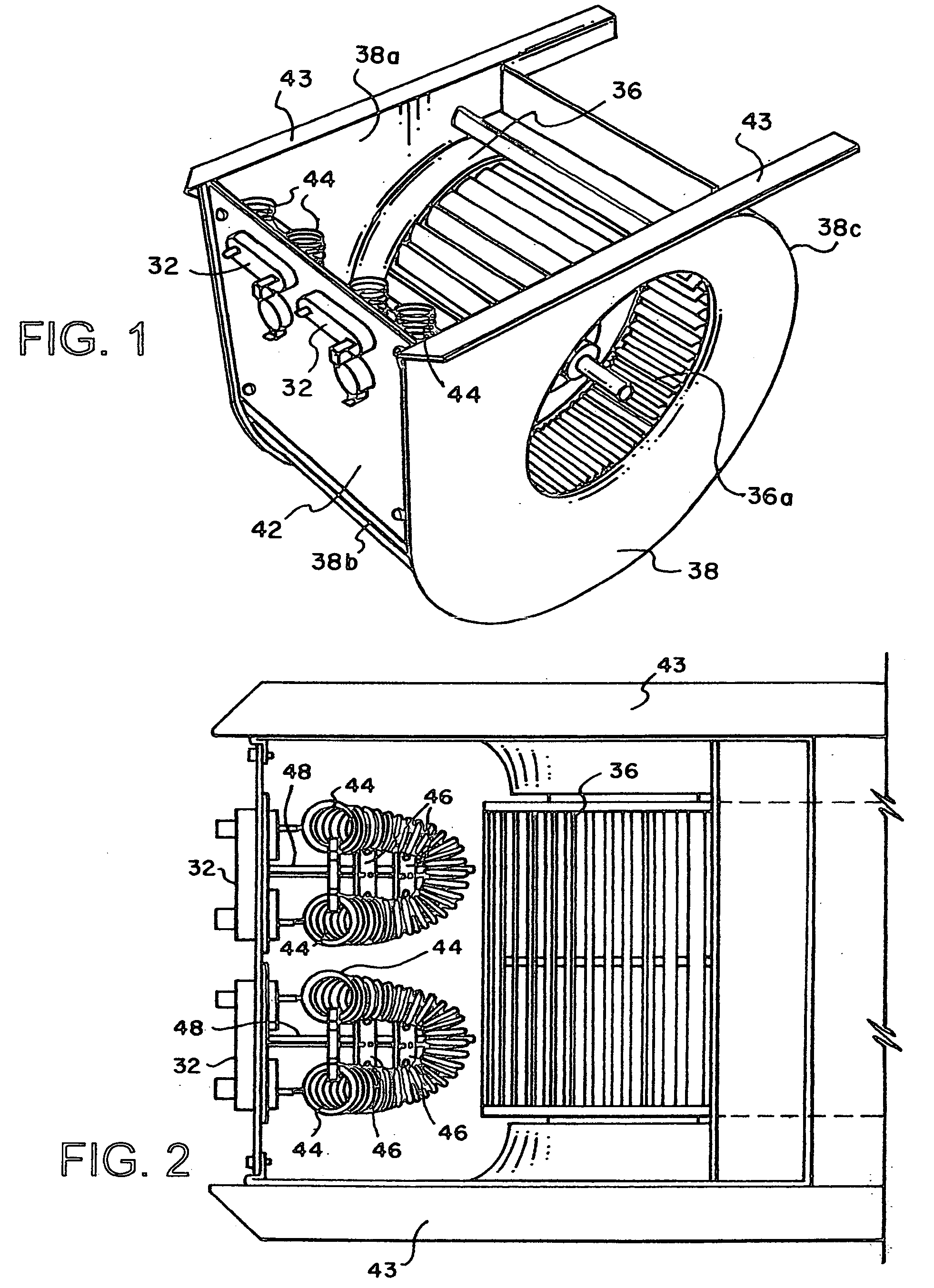
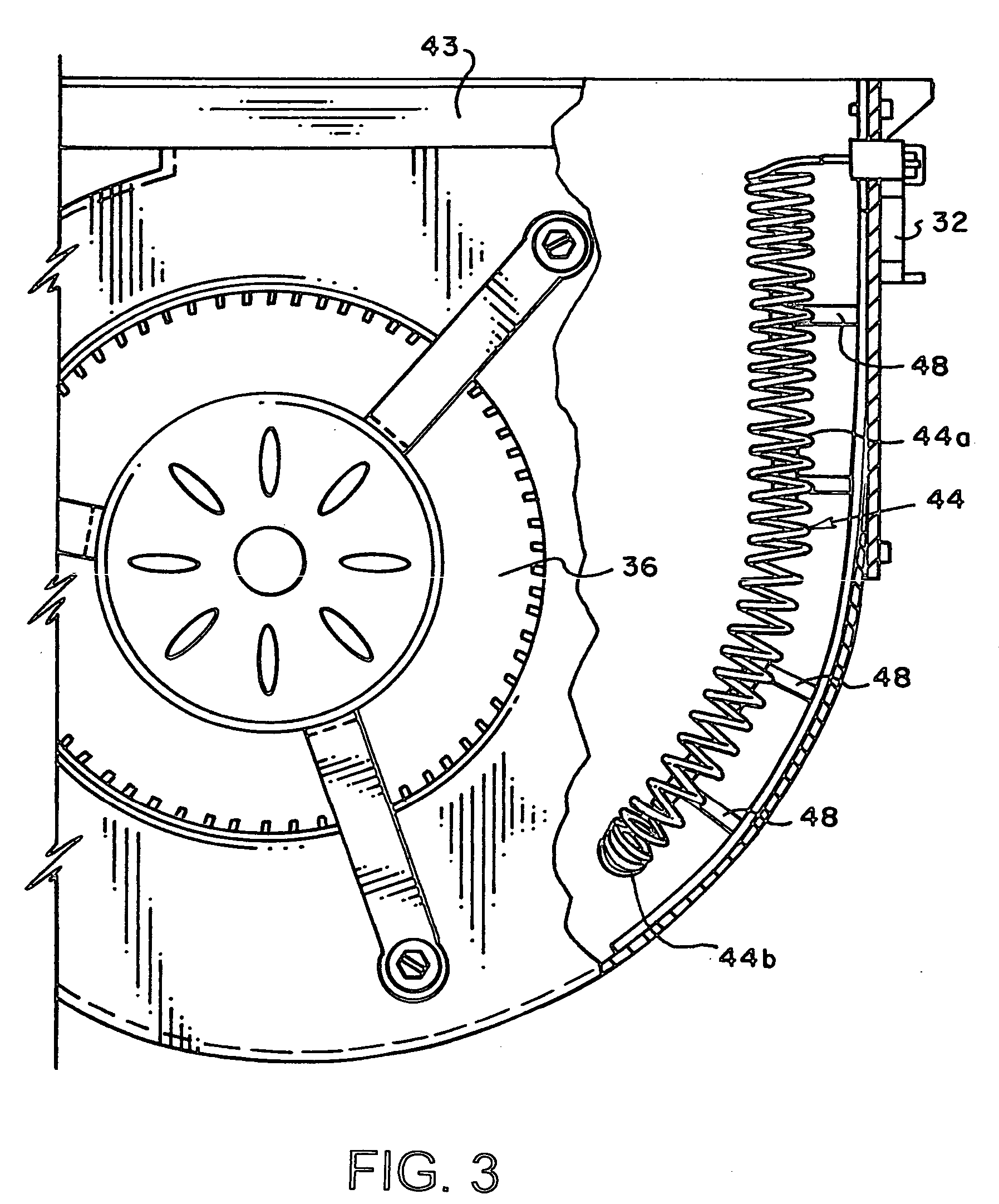
[0005] In accordance with the present invention, air conditioning apparatus is provided in which an air blower and an electric heating assembly are located in a common housing and the heating assembly is removably mounted with the housing. This configuration eliminates the need for a dedicated section in the apparatus for the electric heater downstream of the blower section, which reduces the size of the apparatus. Further, the removability feature facilitates replacement of the heater assembly in the field if a different capacity heater assembly is desired or in the event of a component malfunction.

Problems solved by technology

Although this configuration eliminates the need for a dedicated electric heating section downstream of the blower section, the heating element is not field-replaceable to accommodate different electrical heating capacities.

Method used


Image

  • Air conditioning apparatus with blower and electric heater in common housing
  • Air conditioning apparatus with blower and electric heater in common housing
  • Air conditioning apparatus with blower and electric heater in common housing

Examples


Embodiment Construction

[0020] The best mode for carrying out the invention will now be described with reference to the accompanying drawings. Like parts are marked in the specification and drawings with the same respective reference numbers. In some instances, proportions may have been exaggerated in order to depict certain features of the invention.

[0021] Referring now to FIGS. 5, 7 and 9, a conventional air handling unit 10 used in an electrically powered heating / cooling system, such as a heat pump system, is depicted in an upright position for “upflow” operation. Unit 10 includes a cabinet 11, which houses, from bottom to top, a filter section 12, a heat exchanger section 14, a blower section 16 and an electrical heating section 18. In operation, air to be cooled or heated is drawn into cabinet 11 by an air blower 17 in blower section 16 through a return air duct 19 in communication with the lower front portion of cabinet 11, as indicated by directional arrows 20 in FIGS. 5 and 9, and is first passed ...


PUM


Abstract

Air conditioning apparatus is provided in which an air blower and an electric heater assembly are located in a common housing with the heater assembly projecting into the housing from a wall thereof in transverse relationship to the blower. This configuration eliminates the need for a dedicated space for the electric heater downstream of the blower housing, which reduces the size of the apparatus. The wall of the housing includes an opening through which the heater assembly is insertable into the housing. The heater assembly includes a mounting plate to close off the wall opening and to removably mount the heater assembly with the housing. The heater assembly preferably further includes an open coil electric heater, with a major dimension of the heater being oriented generally parallel to the direction of air flow in the blower housing.

Description

TECHNICAL FIELD [0001] This invention relates generally to air conditioning apparatus and in particular to air conditioning apparatus that includes an electric heater. BACKGROUND ART [0002] The indoor unit of an air conditioning system, which often is referred to as an air handler, typically includes a cabinet having at least a filter section, a heat exchanger section and a blower section. In electrically powered heating / cooling systems, such as heat pumps, the air handler usually also includes an electric heating section having one or more electric heating elements. The heating section is usually located downstream of the blower section in relation to the direction of air flow in the cabinet. One such air handler is shown and described in U.S. Pat. No. 3,977,467. [0003] In operation, air to be cooled or heated is drawn into the cabinet through a return air duct and is first passed through a filter in the filter section to remove dirt and other debris. After the air passes through t...

Claims


Application Information

Patent Timeline
IPC IPC(8): F24F1/0093F24H3/04
CPCF24F1/0007F24F2221/34F24H3/0405F24F2001/004F24F1/005F24F1/0093
Inventor LOGAN, COLBY W.PORTERFIELD, DONALD E.HENSLEY, JERRY L.PICKLE, JAMES W.
Owner ADVANCED DISTRIBUTOR PRODS
Why Eureka
Eureka Blog
Learn More