
Methods and apparatus for mitral valve repair

Inactive Publication Date: 2005-06-30
REALYVASQUEZ FIDEL
View PDF3 Cites 151 Cited by
  • Summary
  • Abstract
  • Description
  • Claims
  • Application Information

AI Technical Summary

Benefits of technology

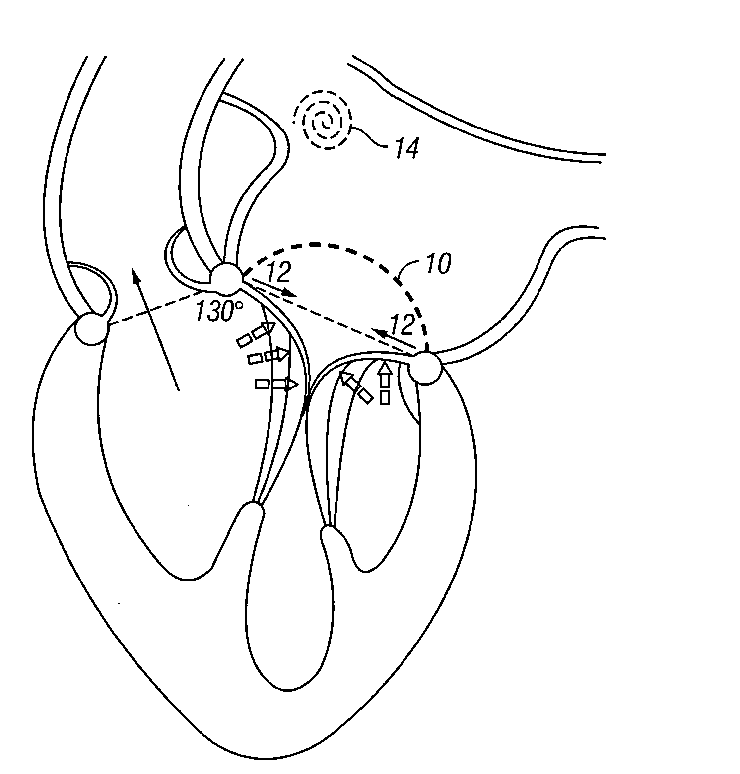
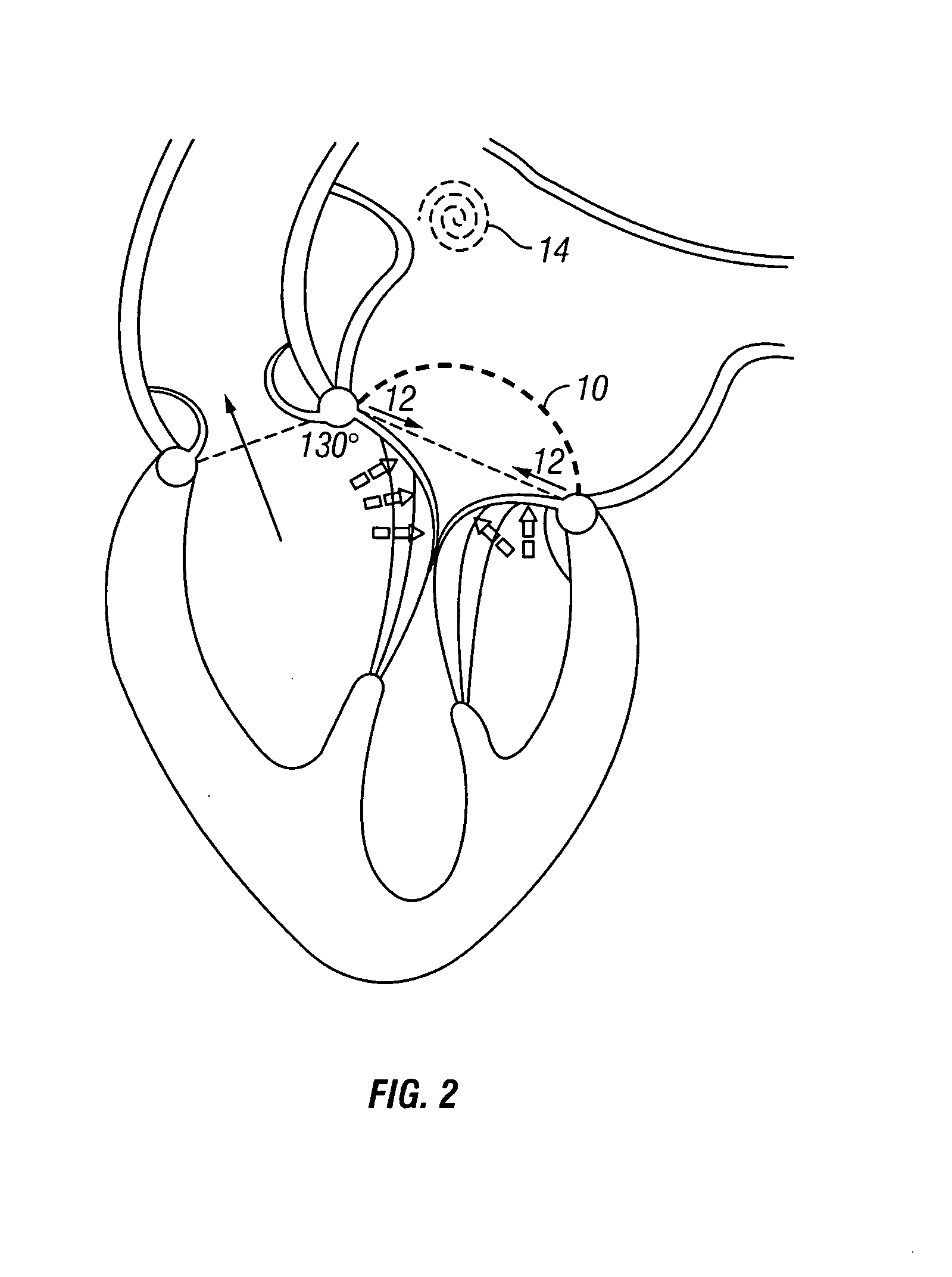
[0015] In one embodiment, the present invention provides a method of improving valve morphology at a target site. The method comprises providing an apparatus having a first configuration, with a reduced outer diameter and a second configuration, with an expanded outer diameter. The apparatus is advanced into the body in the first configuration. The apparatus is expanded into the second configuration. This typically occurs near the target site. A first portion and a second portion of the apparatus are attached to tissue at the target site, wherein attachment brings an anterior leaflet of the valve closer to the posterior leaflet and reduces a gap therebetween. Penetrating members may be advanced into the tissue wherein the penetrating members may act as fasteners to hold the apparatus in place.
[0016] In one embodiment, the apparatus includes a first bridge portion and a second bridge portion. The apparatus may also include at least one base on each bridge portion. Attachment of the first bridge portion and the second bridge portion brings an anterior leaflet of the valve closer to the posterior leaflet and reduces a gap therebetween.

Problems solved by technology

Clinical cardiac decomposition (or heart failure) result from heart valve malfunction, such as mitral insufficiency.
This allows blood to flow into the left atrium, this results in left ventricular overload and if the condition is not corrected, the added workload will eventually cause left ventricular enlargement and dysfunction resulting in heart failure.
Rings of all types used to perform annuloplasty can have an adverse effect on mitral valve function.
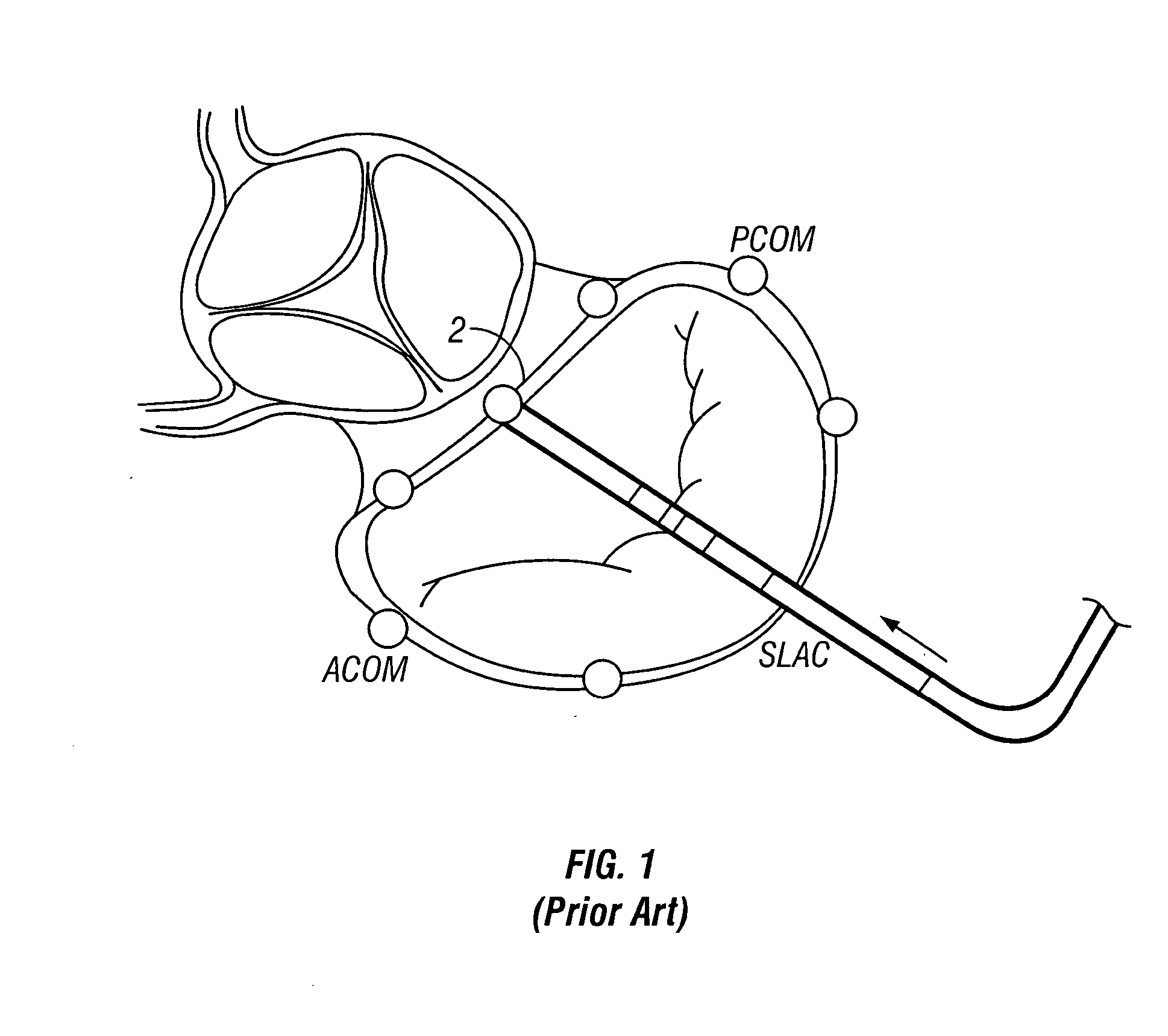
Although Stanford University has done research to validate the concept of SLAC and its efficacy in improving mitral valve performance, there is no technology presently available to perform this procedure in patients.
In trying to achieve SLAC with circumferential or “C” shaped annuloplasty rings (flexible or rigid), however, the end result has been freezing of the posterior leaflet, creation of transvalvular gradient and loss of annular flexibility.
These adverse dynamics can result in stresses placed on the repair.

Method used


Image

  • Methods and apparatus for mitral valve repair
  • Methods and apparatus for mitral valve repair
  • Methods and apparatus for mitral valve repair

Examples


Embodiment Construction

[0029] The present invention provides a solution for treating various valve disorders. Specifically, some embodiments of the present invention provide methods and devices for percutaneous mitral valve repair. For some embodiments of these penetrating member drivers, the invention provides a transvascular solution. At least some of these and other objectives described herein will be met by embodiments of the present invention.

[0030] It is to be understood that both the foregoing general description and the following detailed description are exemplary and explanatory only and are not restrictive of the invention, as claimed. It may be noted that, as used in the specification and the appended claims, the singular forms “a”, “an' and “the” include plural referents unless the context clearly dictates otherwise. Thus, for example, reference to “a material” may include mixtures of materials, reference to “an anchor” may include multiple anchors, and the like. References cited herein are h...


PUM


Abstract

Methods and apparatus are provided for valve repair. In one embodiment, the apparatus includes a first bridge portion and a second bridge portion. The apparatus may also include at least one base on each bridge portion. Attachment of the first bridge portion and the second bridge portion brings an anterior leaflet of the valve closer to the posterior leaflet and reduces a gap therebetween.

Description

CROSS-REFERENCE TO RELATED APPLICATIONS [0001] The present application claims the benefit of priority to co-pending U.S. Provisional Application Ser. No. 60 / 526,663 (Attorney Docket No. 40450-0003) filed Dec. 2, 2003. This application is incorporated herein by reference for all purposes.BACKGROUND OF THE INVENTION [0002] 1. Field of the Invention [0003] The invention relates to methods for valve repair and more specifically to mitral valve repair. The invention is particularly useful in the repair and correction of mitral valve regurgitation. [0004] 2. Description of Related Art [0005] Essential to normal heart function are four heart valves, which allow blood to pass through the four chambers of the heart in one direction. The valves have either two or three cusps or leaflets, which comprise of fibrous tissue that are attached to the walls of the heart. The cusps open when the blood flow is flowing correctly and then close to form a tight seal to prevent backflow. [0006] The four c...

Claims


Application Information

Patent Timeline
IPC IPC(8): A61BA61F2/06A61F2/24
CPCA61F2/2454A61F2/2445
Inventor REALYVASQUEZ, FIDEL
Owner REALYVASQUEZ FIDEL
Learn More