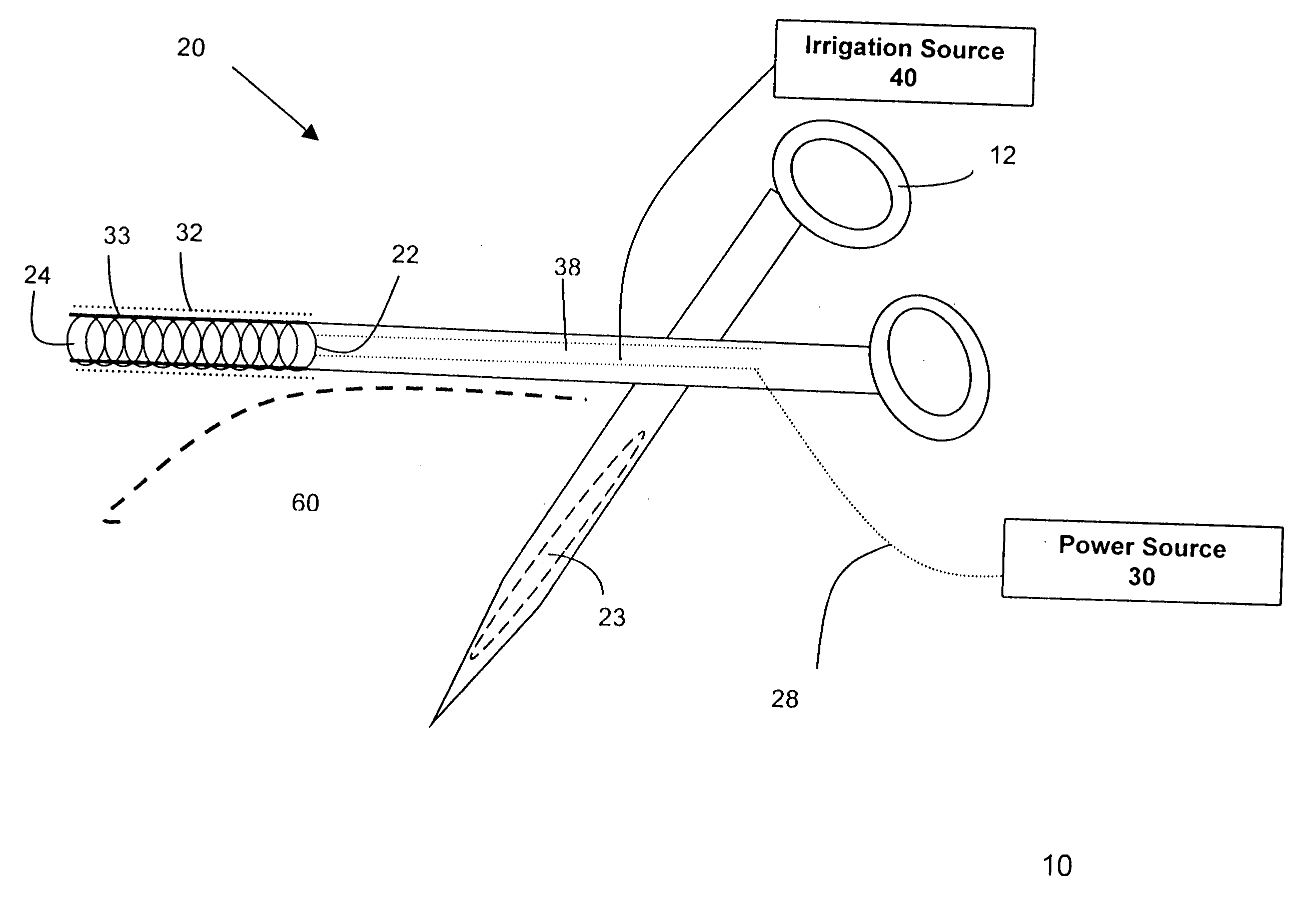
Method of irrigated ablation
a technology of irrigated ablation and irradiation, which is applied in the field of irradiation ablation devices, can solve the problems of non-conductive lesion, blocked electrical pathways within the tissue, and insufficient function of electrical signals
- Summary
- Abstract
- Description
- Claims
- Application Information
AI Technical Summary
Problems solved by technology
Method used
Image
Examples
second embodiment
[0056]FIG. 8 shows a schematic view of a cross-section of a variable length electrode in accordance with the present invention. Conductive element 822 may be for example a double wound coil or spring as described above. Irrigating fluid may be flowed through the lumen 824 of electrode 822. Support element 833 may be for example a slotted tube. Such a slotted tube 833 may be any suitable material that may provide additional structural integrity to conductive element 822. The slotted tube 833 has an opening or slot 834. Preferably this opening 834 may run the length of an entire conductive element 822. This opening 834 may also run the length of an exposed section of a conductive element 822 which has been exposed in a manner as described in the above embodiments. This opening 834 may preferably face a surface of the tissue 860 to be ablated. As shown in FIG. 8, insulating material 832 may cover all of conductive element 822. Insulating material 832 may also cover slotted tube 833. In...
third embodiment
[0057]FIG. 9 shows a schematic view of a cross-section of a variable length electrode in accordance with the present invention. Conductive element 922 may be a slotted tube that also serves as a support element. Irrigating fluid may be flowed through the lumen 924 of electrode 922. The slotted tube 922 has an opening or slot 934. Preferably this opening 934 may run the length of an entire conductive element 922. This opening 934 may also run the length of an exposed section of a conductive element 922 which may be exposed in a manner as described in the above embodiments. This opening 934 may preferably face a surface of the tissue 960 to be ablated. As shown in FIG. 9, insulating material 932 may cover all of conductive element 922. Insulating material 932 may be for example a microporous non-conductive component. Such a microporous non-conductive component may be manufactured from a material such as silicone, PTFE, Dacron fabric or solvent-precipitated polyurethane. Preferably, th...
fourth embodiment
[0058]FIG. 10 shows a schematic view of a cross-section of a variable length electrode in accordance with the present invention. Conductive element 1022 may be, for example a conductive wire located in a non-porous tube 1040. Irrigating fluid may be flowed through the lumen 1024 of tube 1040. The non-porous tube 1040 may have a segment of insulating material 1032. Preferably this segment 1032 may run the length of an entire conductive element 1022. This segment 1032 may also run the length of an exposed section of a conductive element 1022 which has been exposed in a manner as described in the above embodiments. This segment 1032 may preferably face a surface of the tissue 1060 to be ablated. Insulating material segment 1032 may be for example a microporous non-conductive component. Such a microporous non-conductive component may be manufactured from a material such as silicone, PTFE, Dacron fabric or solvent-precipitated polyurethane. Preferably, the pores in the microporous non-co...
PUM
 Abstract
Description
Claims
Application Information
 - R&D
- Intellectual Property
- Life Sciences
- Materials
- Tech Scout
- Unparalleled Data Quality
- Higher Quality Content
- 60% Fewer Hallucinations
Browse by: Latest US Patents, China's latest patents, Technical Efficacy Thesaurus, Application Domain, Technology Topic, Popular Technical Reports.
© 2025 PatSnap. All rights reserved.Legal|Privacy policy|Modern Slavery Act Transparency Statement|Sitemap|About US| Contact US: help@patsnap.com


