
Method for measuring and calibrating measurments using optical fiber distributed sensor

a technology of optical fiber and distributed sensors, applied in the field of fiber optic distributed sensors, can solve the problems of energy loss, change in attenuation, occurrence and effect of other deleterious influences, and difficulty in assessing the introduction of measurement errors

Inactive Publication Date: 2005-06-30
SCHLUMBERGER TECH CORP
View PDF3 Cites 61 Cited by
  • Summary
  • Abstract
  • Description
  • Claims
  • Application Information

AI Technical Summary

Benefits of technology

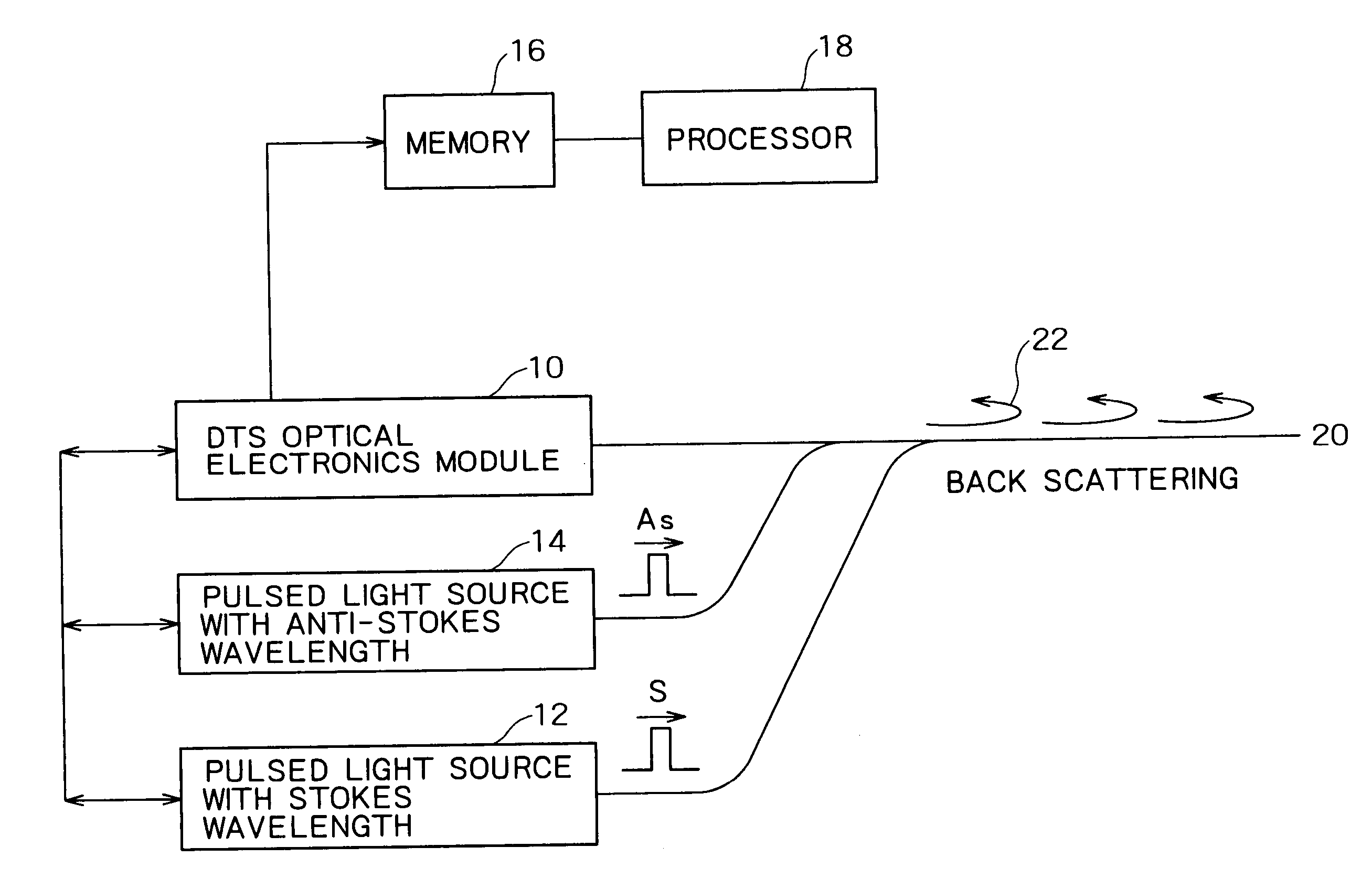
[0017] One embodiment of the present invention is a method of determining temperature along a FO-DTS comprising the steps of: measuring the temperature along an FO-DTS; measuring the temperature at one or more locations along the FO-DTS using at least one independent temperature sensors, determining the difference ΔT1i between the temperature measured using by each of the least one independent temperature sensor and the temperature measuring along the FO-DTS at the respective locations of the at least one independent temperature sensor, and adjusting the temperatures measured by the FO-DTS by ΔT1i, wherein i is the number of independent temperature sensors provided.
[0018] Another embodiment of the present invention is a method of calibrating a FO-DTS, comprising the steps of: measuring the temperature along an FO-DTS; measuring the temperature at one or more locations along the FO-DTS using at least one independent temperature sensors, determining the difference ΔT1i between the temperature measured using by each of the least one independent temperature sensor and the temperature measuring along the FO-DTS at the respective locations of the at least one independent temperature sensor, and using ΔT1i to calibrate temperature determined by the FO-DTS, wherein i is the number of independent temperature sensors provided.
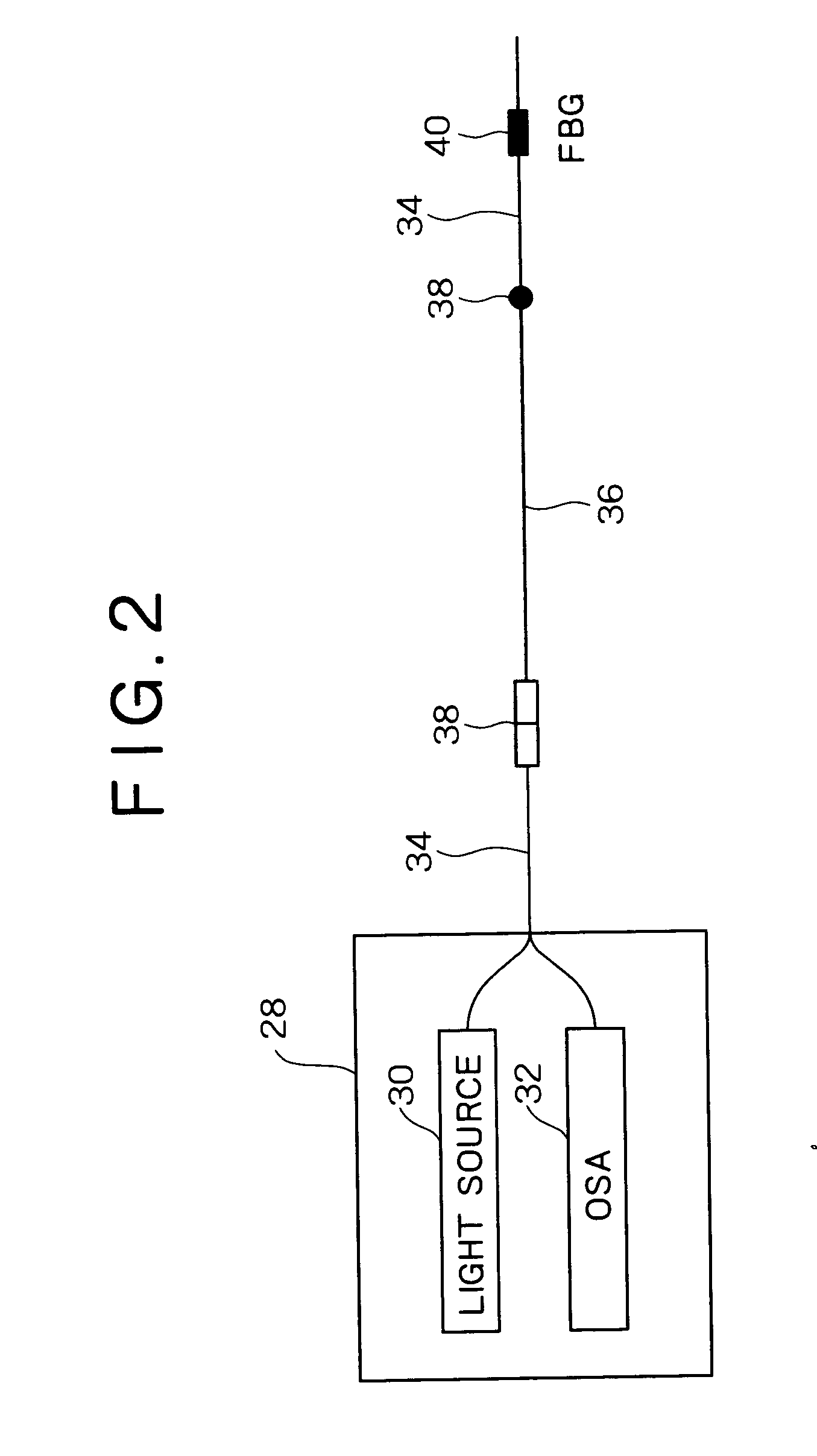
[0019] The present invention includes a method of determining temperature comprising the steps of measuring the temperature along an FO-DTS; measuring the temperature at one or more locations along the FO-DTS using at least one fiber Bragg grating (FBG) in the FO-DTS, determining the difference ΔT2j between the temperature measured using by each of the least one FBG and the temperature measured along the FO-DTS at each respective FBG location, and using ΔT2j to adjust the temperature measured by the FO-DTS, wherein j is the number of FBG temperature sensors provided.
[0020] Another embodiment of the present invention is a method of calibrating a FO-DTS, comprising the steps of: measuring the temperature along an FO-DTS; using at least one FBG in the FO-DTS, measuring the temperature at one or more locations along the FO-DTS using at least one FBG, determining the difference ΔT2j between the temperature measured using by each of the least one FBG and the temperature measuring along the FO-DTS at the respective locations of the at least one FBG, and using ΔT2j to adjust temperatures measured using the FO-DTS, wherein j is the number of FBG temperature sensors provided.
[0021] An embodiment of the present invention is a method of determining temperature along a FO-DTS, comprising the steps of: measuring the temperature along FO-DTS; measuring the temperature at one or more locations along the FO-DTS using at least one independent temperature sensors, determining the difference ΔT1i between the temperature measured by each of the least one independent temperature sensor and the temperature measured along the FO-DTS at the respective locations of the at least one independent temperature sensor, proving at least one FBG in the FO-DTS, measuring the temperature at one or more locations along the FO-DTS using at least one FBG, determining the difference ΔT2j between the temperature measured using by each of the least one FBG and the temperature measuring along the FO-DTS at the respective locations of the at least one FBG, and adjusting the temperatures measured by the FO-DTS based on ΔT1i and ΔT2j, wherein i is the number of independent temperature sensors and j is the number of FBG temperature sensors provided.

Problems solved by technology

Also there may losses owing to environmental stresses like bends or connections.
Parameter measurements obtained using a FO distributed sensor comprise the true parameter measurement and a measurement error caused by deleterious influences on the fiber optic distributed sensor.
By way of example but not limitation, such deleterious influences can include energy losses due to splices or bends, strains in the fiber, changes in attenuation resulting from aging or environmental conditions, drift in measurements over time, hydrogen ingression, or environmental conditions.
While certain measurement errors can be predicted based on manufacturer or material calibration information, baseline testing, or tracking of known elements such as splice location, the occurrence and effect of other deleterious influences and the measurement error they introduce is difficult to assess.
It is known to deploy an optical fiber in a borehole to obtain distributed measurements of borehole parameters and it can be appreciated that accounting for these deleterious influences and their associated measurement error is particularly difficult when the fiber optic distributed sensor is deployed in a borehole.
Maintaining such a reference point may not be feasible.
For example, in downhole application where an optical fiber is disposed in a borehole, it may not be possible to maintain a reference point at a known temperature.
The accuracy of parameter measurements can be limited by the algorithm or methodology used to account for variations in the measurements and such limitations in methodology can exist regardless of whether an optical fiber is deployed in a borehole in a linear or loop configuration.

Method used


Image

  • Method for measuring and calibrating measurments using optical fiber distributed sensor
  • Method for measuring and calibrating measurments using optical fiber distributed sensor
  • Method for measuring and calibrating measurments using optical fiber distributed sensor

Examples


Embodiment Construction

[0034] A concern in using FO distributed sensors is the possible loss of calibration of the FO distributed sensor after deployment due to the change in the fiber characteristics, such as non-uniform attenuation of the fiber along the spectrum caused by micro-bending losses or hydrogen ingression. This concern is particularly heightened when considering long-term deployment of a FO distributed sensor in a borehole environment as changes in the FO cannot be easily monitored, hostile conditions such as high temperature and pressures occur in borehole environments, and the expense of replacing a FO can be significant. This concern can be minimized by methods of calibration to correct measurements made using an in situ FO distributed sensor. Such methods of calibration include calculating an expected change in SAR with time, providing at least one calibrating sensor or FBG along the FO distributed sensor, providing measurements from each end of a loop configuration FO distributed sensor,...


PUM

PropertyMeasurementUnit
temperatureaaaaaaaaaa
lengthaaaaaaaaaa
lengthaaaaaaaaaa

Abstract

Methods for calibrating and making measurements using fiber optic sensors are disclosed using backscattered wavelengths and independent sensors. The disclosure sets outs methods applicable with fiber optic sensors either in a deployed in a loop and in a linear configuration and useful for measurements including temperature.

Description

BACKGROUND OF THE INVENTION [0001] The invention relates to fiber optic distributed sensors and methods of measuring parameters and calibrating parameter measurements made using optical fiber distributed sensors. In particular, methods of measuring temperature and calibrating temperature measurements made using fiber optic distributed temperature sensors are disclosed. DESCRIPTION OF RELATED ART [0002] Optical fibers typically include a core, a concentric cladding surrounding the core, a concentric protective jacket or buffer surrounding the cladding. Generally the core is made of transparent glass or plastic possessing a certain index of refraction and the cladding is made of transparent glass or plastic possessing a different index of refraction. The relative refractive indices of the core and the cladding largely determine the function and performance of the optical fiber. As a beam of light is introduced into the optical fiber, the velocity and direction of the light changes at ...

Claims


Application Information

Patent Timeline
Patent Type & Authority Applications(United States)
IPC IPC(8): G01K11/12G01D5/353G01J5/08G01J5/10G01K11/32G01N21/65
CPCG01K11/32G01K11/3206G01D5/35364G01K15/002G01K15/00G01D5/353G01D5/35383G01N21/65
Inventor YAMATE, TSUTOMUSCHROEDER, ROBERT J.RAMOS, ROGERIO T.MULLINS, OLIVER C.
Owner SCHLUMBERGER TECH CORP
Learn More