
Remote identification of container contents by means of multiple radio frequency identification systems

Active Publication Date: 2005-06-23
QUAKE GLOBAL
View PDF6 Cites 117 Cited by
  • Summary
  • Abstract
  • Description
  • Claims
  • Application Information

AI Technical Summary

Benefits of technology

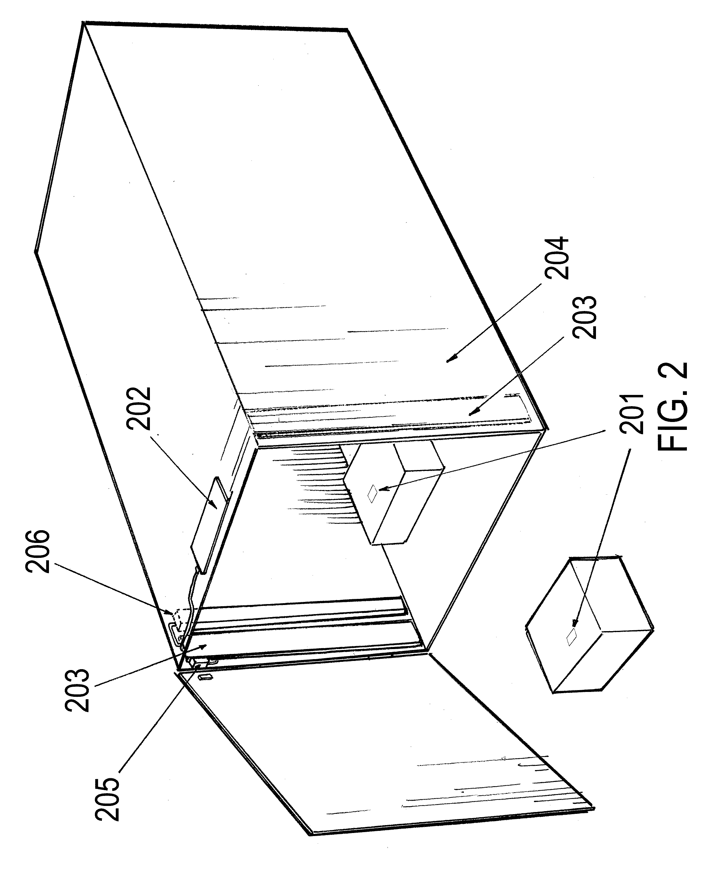
[0011] When the container is closed, the mechanical switch, which is affixed to its opening, signals to the on-board interrogator that it should function for a preset period of time. The interrogator then queries RF tags within its interior and reads their IDs into stored memory within the externally accessible RF tag attached to the container. When the external interrogator polls the externally accessible RF tag or detects the externally accessible RF tag”s beacon, it acquires the inventory of the internal tags that was established at the time the container was closed. Because the externally accessible RF tag may be an active tag with significant stored power, a potentially more effective frequency, and with less shielding by the container walls, it may have a much greater range and capacity to surmount obstacles than the RF tags within the container. The structure of the container, externally accessible RF tag, and antenna may be configured such that a desired successful read rate can be achieved given known configurations of containers. The apparatus allows for automatic translation between RFID systems: while the container”s interior may be populated with RF tags that cannot by read by an external interrogator, as long as the externally accessible RF tag is compatible, the entire group represented by the container and its contents may be inventoried by the external interrogator.

Problems solved by technology

Generally, less expensive RFID systems have lesser capabilities.
For instance, passive tags may have very low cost per unit, facilitating widespread use, but they also have limited range.
RFID systems may also fail when applied to groups of objects, containers of multiple objects, or nested containers of objects.
For shipping and warehousing of large containers on pallets, which often contain nested containers, inexpensive passive tags on individual objects may not provide adequate identification rates.
Human manipulation of such objects may afford acceptable identification rates, but it also increases the cost of identifying each object.
Active tags have greater range, but they may be impractical in many instances because of cost, shelf life, RF interference or other reasons.

Method used


Image

  • Remote identification of container contents by means of multiple radio frequency identification systems
  • Remote identification of container contents by means of multiple radio frequency identification systems
  • Remote identification of container contents by means of multiple radio frequency identification systems

Examples


Embodiment Construction

[0018] The following detailed description of embodiments of this invention and the attached figures are intended to provide a clear description of the invention without limiting its scope.

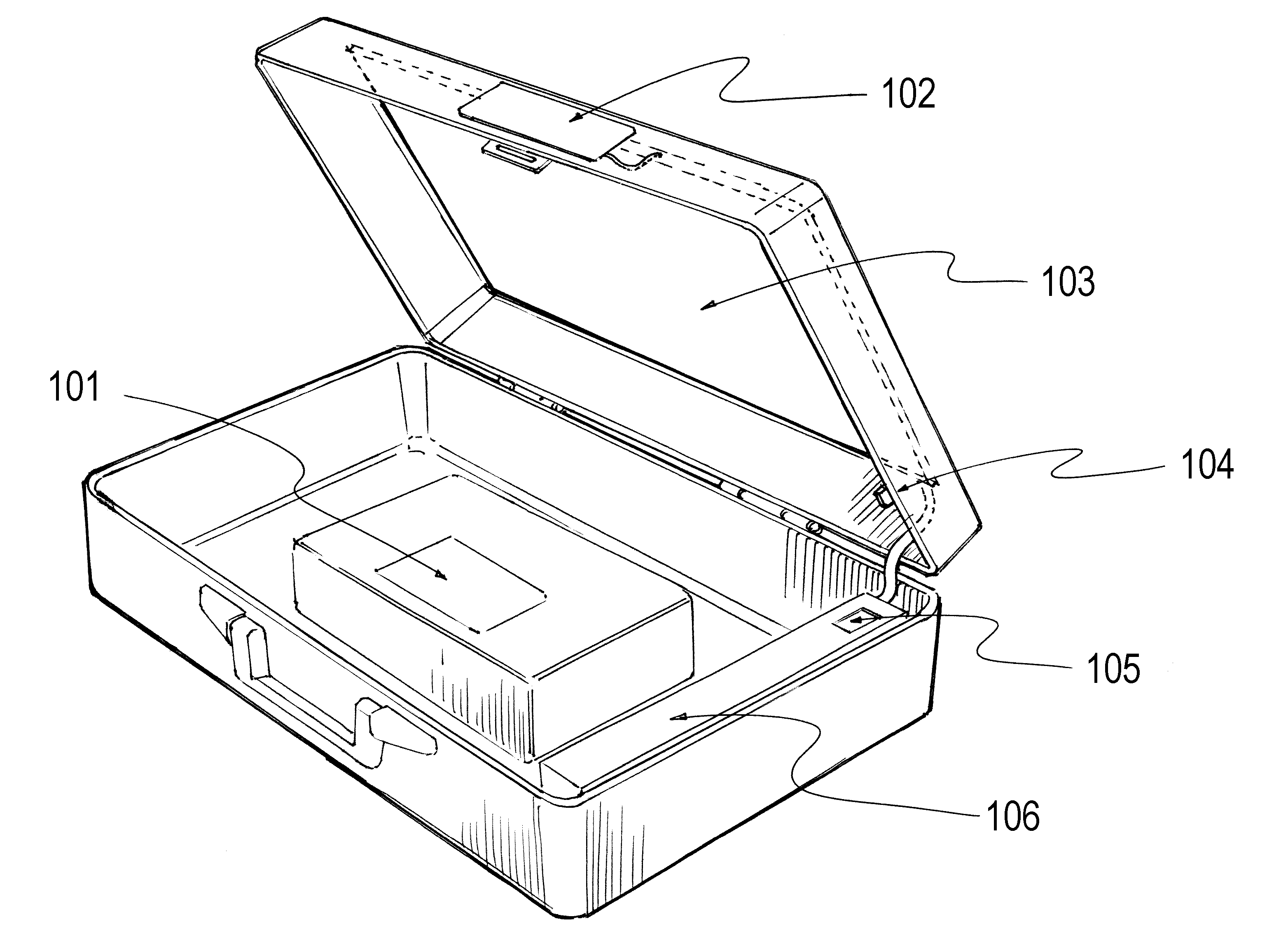
[0019]FIG. 1 is a diagram illustrating an embodiment of the invention, incorporated in an attache case. The RF tag 101 is attached to an object or objects within the attache case. In this embodiment, the RF tag 101 is a passive tag operating at 125 kHz, 13.56 MHz, or 900 MHz. The shape of the objects within the attache, the shape of the attache, and the orientations of the RF tags with respect to the objects and the interrogator / interrogator antenna 103 ensure that the rate of successful read operations performed by the interrogator upon the interior objects is optimal. In an alternate embodiment, compartments or dividers or multiple interrogators might perform the same function for containers and objects of different geometries. Externally accessible RF tag 102 is an active or semi-passive tag th...


PUM


Abstract

A method and apparatus for performing the remote identification of the contents of containers by means of multiple radio frequency identification systems.

Description

BACKGROUND OF INVENTION [0001] This invention relates to a method and apparatus for performing the remote, real-time identification of the contents of containers by means of multiple radio frequency identification systems. [0002] Radio Frequency ID (RFID) systems allow for the identification of objects at a distance and out of line of sight. They are comprised of transponders called radio frequency (RF) tags and RF interrogators (also called readers). The tags are smaller, sometimes as small as a grain of rice, less expensive than interrogators, and are commonly attached to objects such as product packages in stores. When an interrogator comes within range of an RF tag, it may provide power to the tag via a querying signal, or the RF tag may use stored power from a battery or capacitor to send a radio frequency signal to be read by the RFID interrogator. [0003] RF tags may consist of single integrated circuits, circuits and antennae, or may incorporate more complex capabilities such...

Claims


Application Information

Patent Timeline
IPC IPC(8): G06K7/08G06K17/00H04Q5/22
CPCG06K7/10336G06K2017/0045G06K17/00
Inventor SWEENEY, PATRICK JOSEPH II.
Owner QUAKE GLOBAL
Learn More