
Pressure adjustment mechanism, liquid tank, liquid providing device, ink cartridge, and inkjet printing apparatus

a technology of pressure adjustment mechanism and inkjet printer, which is applied in printing and other directions, can solve the problems of large weight of the entire carriage, inability to control the inside pressure of the suntank to be a desired value, and the use of expensive motors or solenoid devices is wise, and achieves the effect of low driving for

Inactive Publication Date: 2005-06-02
RICOH KK
View PDF9 Cites 40 Cited by
  • Summary
  • Abstract
  • Description
  • Claims
  • Application Information

AI Technical Summary

Benefits of technology

[0026] It is a general object of the present invention to provide a pressure adjustment mechanism that enables a relatively low driving force used for operation of a subtank that holds ink, and an inkjet printer that uses this pressure adjustment mechanism.
[0027] It is another object of the present invention to provide a liquid tank in which a negative pressure in the liquid tank can be adjusted without increasing waste ink, with a simple structure.
[0028] It is another object of the present invention to provide a liquid providing device that can reliably provide liquid to a printing head or the like for a long time.

Problems solved by technology

Accordingly, in terms of the manufacturing costs of the printer, it is not wise to use the expensive motor or solenoid for the air releasing filling operation having the less necessary frequency.
Furthermore, in this case, the inside pressures of the suntanks cannot be controlled to be a desired value.
On the other hand, when the capacity of the ink cartridge is made large, the weight of the entire carriage becomes large.
Accordingly, it becomes difficult to move the carriage at a high speed, and further, the size of the carriage and the like becomes large.
In addition to that, the output energy of the motor for driving the carriage needs to be large.
Moreover, the weight of the carriage changes significantly, so that the movement characteristics of the carriage change during the printing operation, and it becomes difficult to maintain stable printing accuracy.
However, the ink is wasted without being used, and the absorbing body for holding the waste ink in the printer becomes larger.
In addition, using the only ink cartridge disposed on the carriage causes the ink shortage more often.
Since the disclosed printers do not have a function of discharging the air mixed with the ink inside the ink supply passage (the tube), a large amount of air enters the subtank when the tube is used for a long time, resulting in printing being degraded.
Accordingly, it is necessary to arrange the plural long tubes in the printer, and to provide a special pump for generating the negative pressure, resulting in high manufacturing costs.

Method used


Image

  • Pressure adjustment mechanism, liquid tank, liquid providing device, ink cartridge, and inkjet printing apparatus
  • Pressure adjustment mechanism, liquid tank, liquid providing device, ink cartridge, and inkjet printing apparatus
  • Pressure adjustment mechanism, liquid tank, liquid providing device, ink cartridge, and inkjet printing apparatus

Examples


third embodiment

[0132] the negative pressure in the ink tank 101 is generated by opening and closing the air releasing opening of the ink tank 101, and changing the inside capacity of the ink tank 101. Accordingly, the ink can be supplied to the ink tank 101 without increasing the waste ink produced at the time of the ink supply and without degrading the quality of the ink in the main ink cartridge.

[0133] Furthermore, as another method of generating the negative pressure in the ink tank 101, after the ink is provided to the ink tank 101, and the air releasing valve 108 is closed to make the closed state of the ink tank 101, the negative pressure can be generated by discharging the ink from the ink tank 101 via the head. This method may be applied, but the ink discharged from the head is wasted. Accordingly, the above method of generating a negative pressure by changing the capacity of the ink tank is superior to the method of generating a negative pressure by discharging the ink in that the wasted...

fourth embodiment

[0136] Next, the present invention will be described with reference to FIGS. 15 and 16. In FIG. 15, the basic structure of an ink providing device including an ink tank is shown, and in FIG. 16, the operation of the ink providing device is shown.

[0137] In the forth embodiment, the difference in the pressure head between the ink tank 101 and the main cartridge 132 is used instead of the supply pump 134 used in the third embodiment.

[0138] With this structure, it is possible to provide the ink to the ink tank 101 from the main cartridge 132 by using the difference in the pressure head. In this case, since the pump is not necessary, the ink providing device can be manufactured at a low cost.

[0139] In this embodiment, as a method of providing the ink to the subtank from the main cartridge, the main cartridge 132 may be made of flexible materials so that the pressurized ink can be provided to the subtank from the main cartridge by deforming the main cartridge.

[0140] Next, a fifth embod...

fifth embodiment

[0141] In the fifth embodiment, a displacement member (or a moving member) 109 is provided at an ink tank 101. The displacement member 109 can move or rotate, centering the point “a” of FIGS. 18 and 19, in accordance with the deformation of the film 103. The displacement member 109 is made of a leaf spring or the like. The spring force of the displacement member 109 is set to be weaker than the spring force of a compressed spring 104 provided in the ink tank 101. The displacement member 109 is moved in accordance with the deformation of the film 103, i.e., the increase or the decrease of the ink in the ink tank 101. Displacement detection means 136 includes a transmission photo sensor for detecting the displacement of the displacement member 109 by detecting the existence or absence of a detection piece 109a provided at the end of the displacement member 109 of the ink tank 101.

[0142] With this structure, when the ink in the ink tank 101 is consumed, as shown in FIG. 19, the film 10...


PUM


Abstract

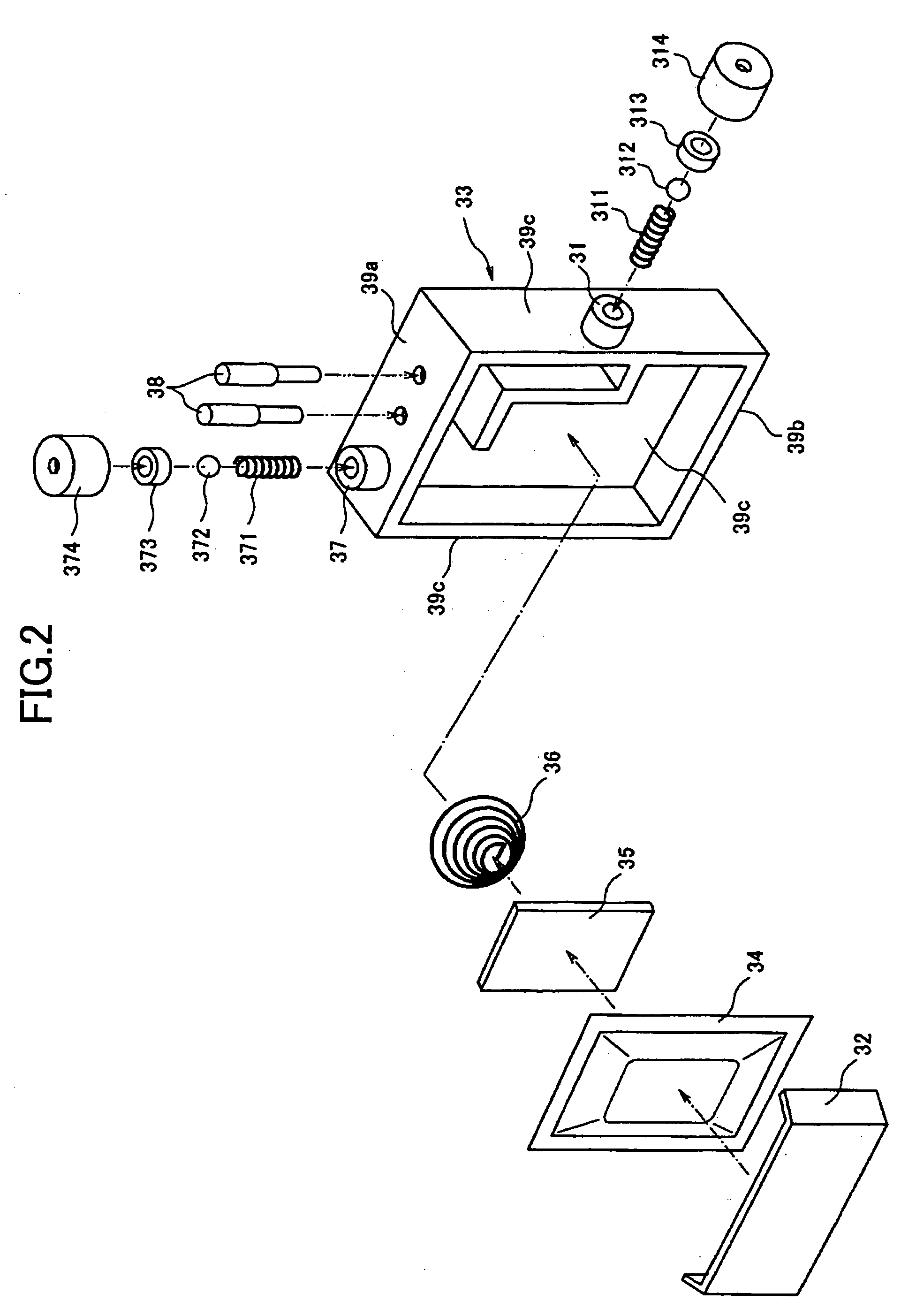
A pressure adjustment mechanism can provide ink to a subtank with the inside of the subtank being opened to outside air, by using a low driving force. A liquid tank holds liquid to be used by a printing apparatus. The liquid tank has a structure in which a capacity of the liquid tank can be changed so as to generate a negative pressure in the liquid tank. The liquid tank includes a case having an opening at one side of the tank, and a flexible film that covers the opening, and a compressed spring in the tank for pressing the film outwards.

Description

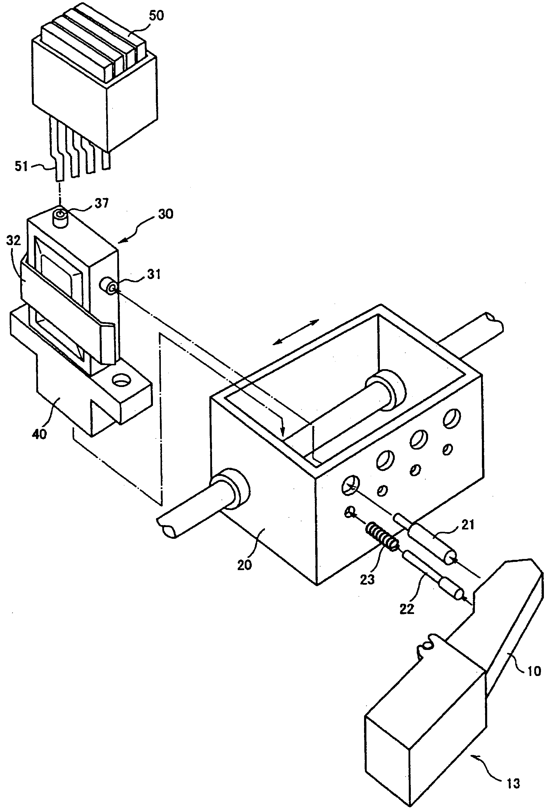
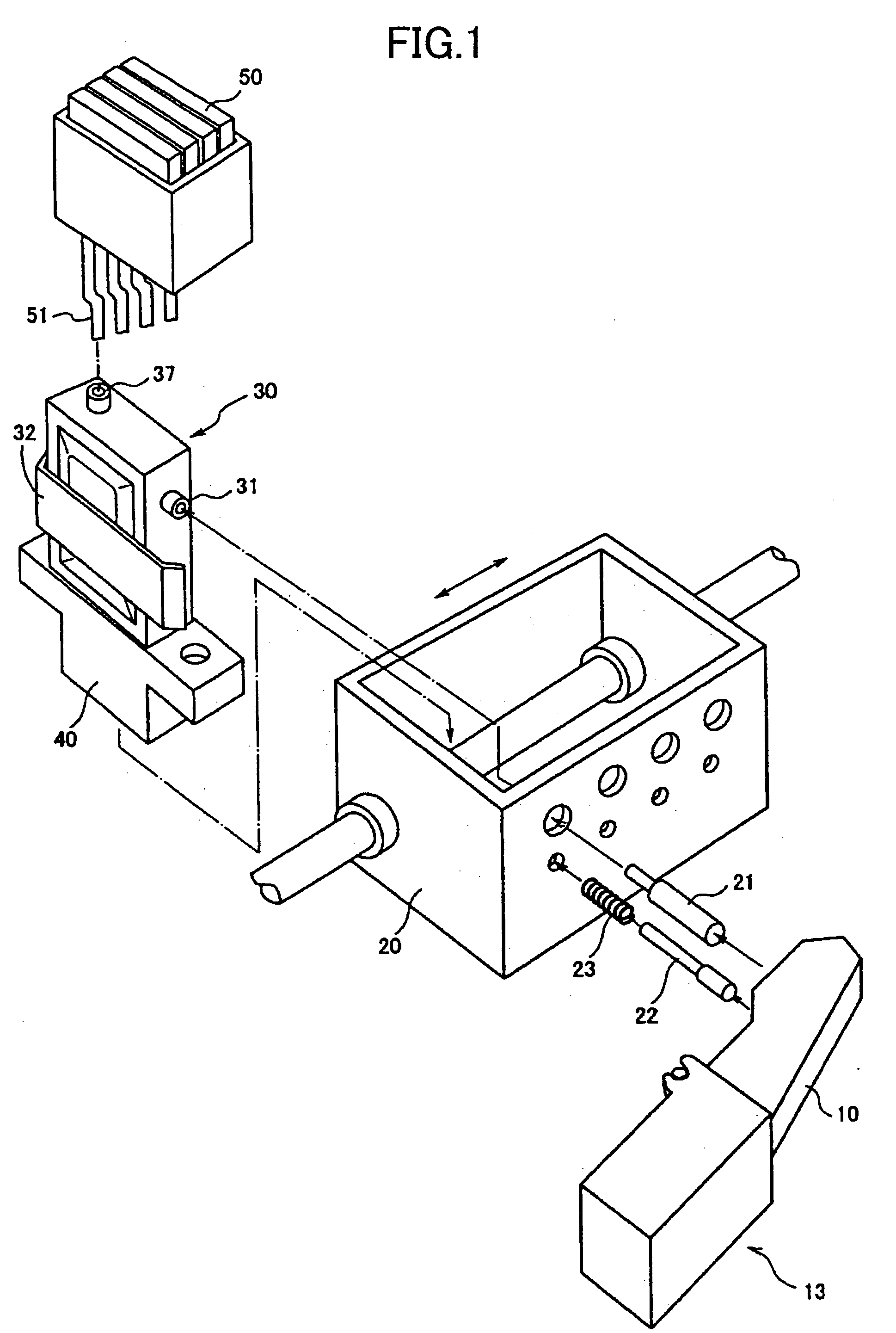
TECHNICAL FIELD [0001] The present invention relates to a pressure adjustment mechanism for an inkjet head device, and an inkjet printer that uses the pressure adjustment mechanism. Specifically, with this pressure adjustment mechanism, a driving mechanism can use a low driving force when ink is provided to an ink subtank provided at the inkjet head device with the inside of the subtank being open to the outside air. Specifically, the inkjet printer uses the pressure adjustment mechanism to provide ink to the inside of the subtank while adjusting a pressure of the subtank. [0002] The present invention also relates to a liquid tank, a liquid providing device, an ink cartridge, and an inkjet printer (inkjet printing apparatus). BACKGROUND ART [0003]FIG. 1 is a perspective view showing disassembled elements that are used at a conventional inkjet head device of an inkjet printer. In FIG. 1, the reference number 10 designates a lever, 13 a driving mechanism for driving the lever 10, 20 a...

Claims


Application Information

Patent Timeline
IPC IPC(8): B41J2/175
CPCB41J2/17503B41J2/17556B41J2/17553B41J2/17513
Inventor KATOH, TOMOMIHORI, EISUKE
Owner RICOH KK
Learn More