Display device

a display device and display technology, applied in static indicating devices, electroluminescent light sources, instruments, etc., can solve the problems of variable luminance and point of operation, and achieve the effect of constant luminan

Active Publication Date: 2005-05-26
SANYO ELECTRIC CO LTD
View PDF4 Cites 42 Cited by
  • Summary
  • Abstract
  • Description
  • Claims
  • Application Information

AI Technical Summary

Benefits of technology

[0036] Because the change with temperature and time of the display element is slow, a new correction coefficient need not be calculated at the same cycle as the frame cycle of the video signal. The suitable correction in accordance with the change with temperature and time can be made to the video signals by the use of the correction coefficient calculated at a longer cycle than the frame cycle. According to the specific construction described, the cycle of the setting operation of the video signal setting means is set to the cycle described. This can suppress a flicker in the screen.
[0043] As stated above, with the first and the second display devices of the present invention, a constant luminance can be achieved despite the change with temperature and time of the display element.

Problems solved by technology

However, the organic LED display device described has the problem that the organic EL characteristics are shifted due to change with temperature and time of the organic EL element, as shown in FIG. 17, causing a point of operation to be shifted, whereby a luminance is varied.

Method used


Image

  • Display device
  • Display device
  • Display device

Examples


first embodiment

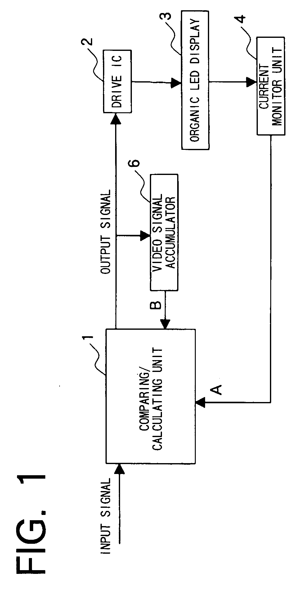
[0062]FIG. 1 shows an organic LED display device of the present embodiment. A video signal from a video source such as a TV receiver is fed to an A / D converter which is not shown, converted into digital data, and thereafter fed to a comparing / calculating unit 1 for processing the signal and correcting the signal as required for video display as will be stated below. The video data of RGB three primary colors thus obtained is fed to a drive IC 2. Data voltage corresponding to the data is fed to each pixel of an organic LED display 3. Drive current corresponding to the data voltage is fed to an organic EL element of each pixel to cause the organic EL element to luminesce.

[0063] The organic LED display device of the present embodiment is adapted to divide a display area of the organic LED display 3 into a plurality of areas as indicated in a broken line in FIG. 3, and to make a correction to the video data for each of the areas and for each color of the RGB three primary colors. The c...

second embodiment

[0078] With the organic LED display device of the first embodiment, the video data is corrected corresponding to the change with temperature and time. With the organic LED display device of the present embodiment, the relationship between the video data and the data voltage is changed.

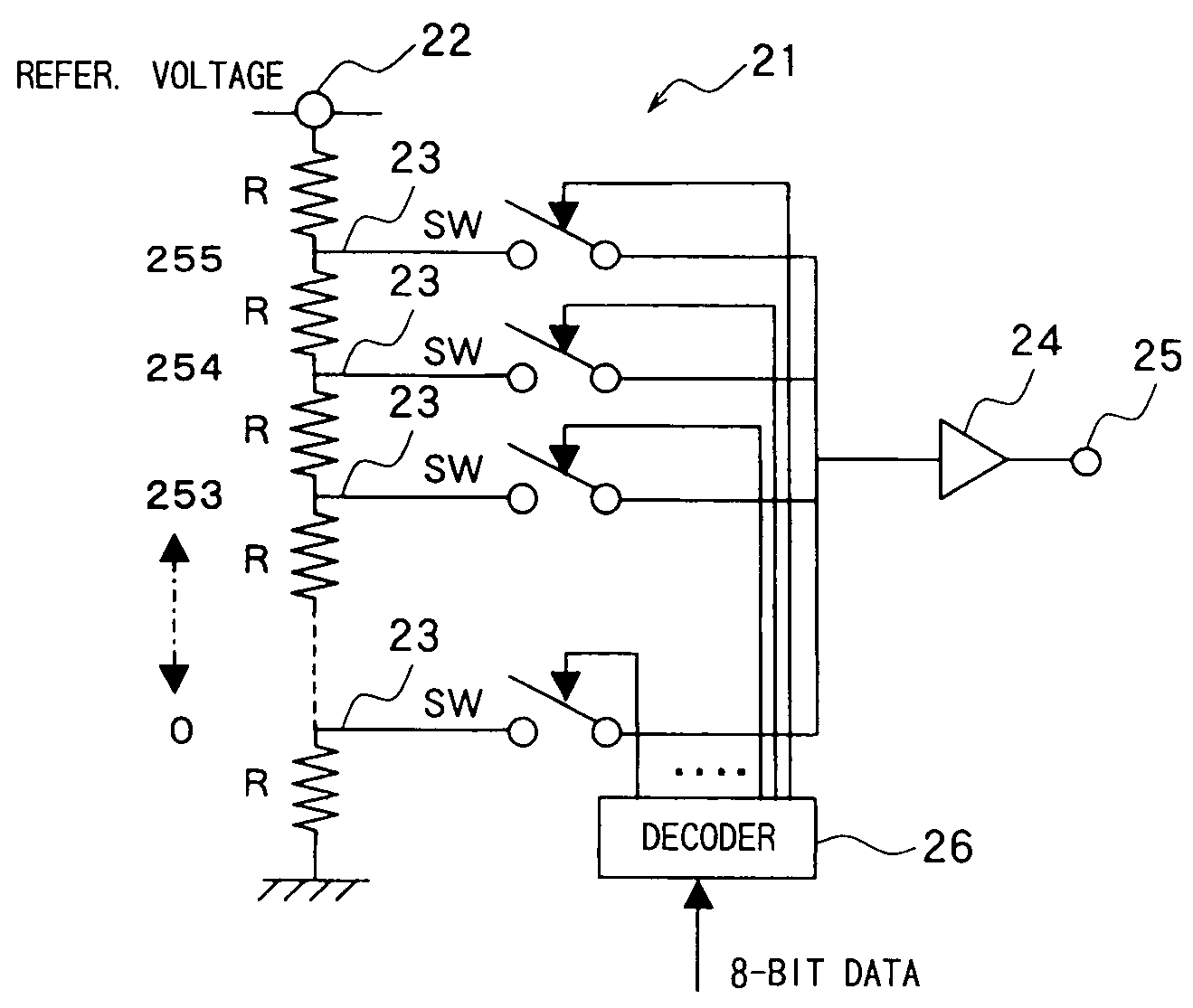
[0079]FIG. 9 shows an organic LED display device of the present embodiment. A video signal from a video source such as a TV receiver is fed to an A / D converter which is not shown, converted into digital data, and thereafter fed to a comparing / calculating unit 10 for processing the signal and correcting the signal as required for video display. The 8-bit-long video data of RGB three primary colors thus obtained is fed to a drive IC 20. The drive IC 20 changes the relationship between the video data and the data voltage based on a control signal obtained from the comparing / calculating unit 10, as will be described later. In accordance with the changed relationship, the data voltage corresponding to the ...


PUM


Abstract

The present invention provides a display device comprising a display having an arrangement of a plurality of pixels, a drive IC for supplying to each pixel of the display data voltage or data current corresponding to a video signal fed from the outside, comparing / calculating unit for supplying the video signal to the drive IC, and a current monitor unit for measuring the total quantity of currents to have been passed through a plurality of pixels of the display. The comparing / calculating unit derives the sum of currents to be passed through each pixel of the display based on the values of the video signals for each pixel of the display, to correct the video signals for each pixel of the display based on the derived value and measurement value obtained by the current monitor unit.

Description

BACKGROUND OF THE INVENTION [0001] 1. Field of the Invention [0002] The present invention relates to display devices, such as organic electroluminescence display devices, which include a display panel comprising an arrangement of a plurality of pixels. [0003] 2. Description of Related Art [0004] Progress has been made in developing organic electroluminescence displays (hereinafter referred to as “organic LED displays”) in recent years. Use of organic LED displays, for example, in portable telephones is under study. [0005] The methods of driving such organic LED displays include the passive matrix driving method wherein the scanning electrodes and the data electrodes are used for time division driving, and the active matrix driving method wherein each pixel is held luminescent for one vertical scanning period. Furthermore, the methods of driving the organic LED display devices of the active matrix driving method include the display devices of the analog drive type wherein current of ...

Claims


Application Information

Patent Timeline
IPC IPC(8): G09G3/20G09G3/30H05B33/12G09G3/32G09G3/34G09G5/00H01L51/50H05B33/14H05B44/00
CPCG09G3/3225G09G3/3275G09G2310/027G09G2320/0285H05B33/0866G09G2320/043G09G2320/048G09G2330/02G09G2320/029H05B45/24G09G2310/0259
Inventor INOUE, MASUTAKAYAMASHITA, ATSUHIRO
Owner SANYO ELECTRIC CO LTD
Why Eureka
Try Eureka