Compact mirrored contact lens case

Inactive Publication Date: 2005-05-26
EASTMAN MICHAEL ANTHONY
View PDF10 Cites 14 Cited by
  • Summary
  • Abstract
  • Description
  • Claims
  • Application Information

AI Technical Summary

Benefits of technology

[0012] The present invention comprises a novel contact lens case that provides a compactly configured storage container for storing contact lenses and a reflective surface for conveniently viewing the insertion and abstraction of the contact lens into or from the eye. The contact lens case is design so that it can be inexpensively molded out of a polymer. The contact lens case includes two reservoirs that share a common circular bottom wall. The reservoirs are coaxially oriented and are threaded to accept cylindrical closer caps that seal the reservoirs from loss of fluid and the entry of contaminants. The cylindrical closure caps engage the opposite ends of the cylindrical body and have inner peripheral surfaces that are coaxially related to the outer peripheral surfaces of the two cylindrical reservoirs of the body. Furthermore, the top-end surface of one or more of the cylindrical closure caps has adhered to or embedded into said cylindrical closure cap a reflective surface, a mirror for example, allowing, as its primary function, the user to view the insertion or abstraction of the contact lens into or from the eye. The user will hold the cylindrical closure cap containing the reflective surface (e.g. mirror) directly in front of the eye with one hand while inserting or abstracting the contact lens into or from the same eye with the opposite hand. Thus allowing the user to view, at close proximity, the action heretofore described.

Problems solved by technology

These problems may include the drying of the contact lenses, or a foreign object in their eye, such as a dirt particle or eyelash.
Currently, an additional device with a reflective surface must be carried on the user's person when these situations occur, or, oftentimes, a reflective surface is not conveniently located or available at all when these situations occur.

Method used


Image

  • Compact mirrored contact lens case
  • Compact mirrored contact lens case
  • Compact mirrored contact lens case

Examples


Embodiment Construction

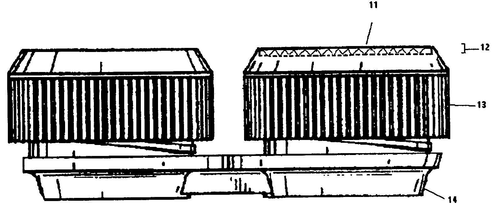
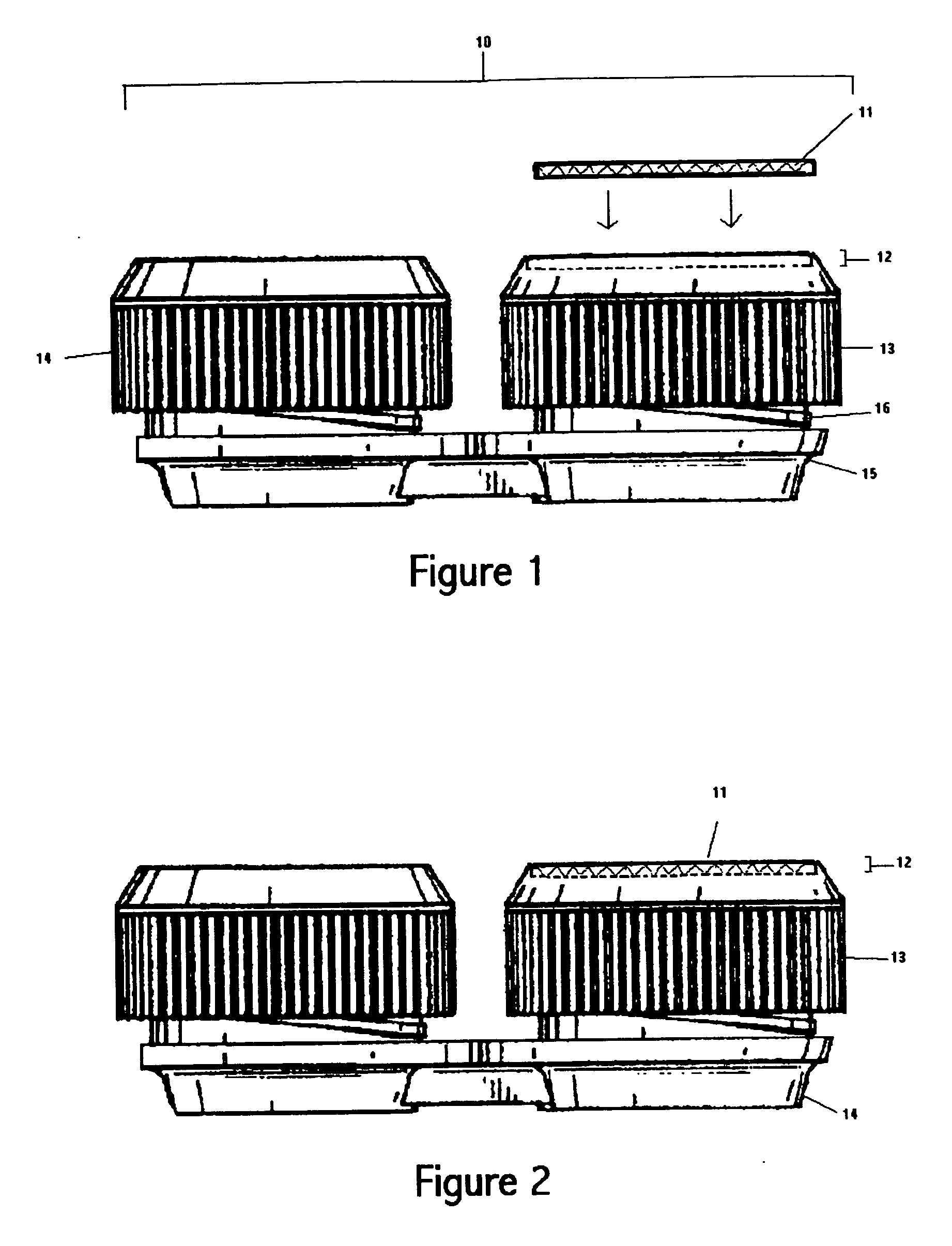
[0022] While the present invention will be described fully hereinafter with reference to the accompanying drawings, it is understood at the outset that the following description will, rather broadly, describe one embodiment of the invention in order that the present contribution to the art may be better appreciated. In this respect, before explaining at least one embodiment of the invention in detail, it is to be understood that the invention is not limited in its application to the details of construction and to the arrangements of the components set forth in the following description or illustrated in the drawings. The invention is capable of other embodiments and of being practiced and carried out in various ways. Also, it is to be understood that the phraseology and terminology employed herein are for the purpose of description and should not be regarded as limiting. As such, those skilled in the art will appreciate that the conception, upon which this disclosure is based, may r...


PUM


Abstract

A compactly configured contact lens case for storing contact lenses which includes at least one mirrored closure cap. The mirror is viewable as the top surface of the closure cap. The contact lens case includes two reservoirs that share a common base and are coaxially oriented and threaded to accept cylindrical closure caps that engage the opposite ends of the cylindrical body and have inner peripheral surfaces that are coaxially related to the outer peripheral surfaces of the two cylindrical reservoirs of the body. The mirrors' primary function is to provide a close proximity view of the insertion or abstraction of the contact lens into or from the users' eye. The user will hold the mirrored closure cap directly in front of the eye with one hand, while performing the act of inserting or abstracting the contact lens into or from the eye with the opposite hand.

Description

BACKGROUND OF THE INVENTION [0001] 1. Field of the Invention [0002] This invention relates generally to contact lens cases and more particularly to a novel contact lens case that is designed to have a compact configuration, while providing a reflective surface (e.g. mirror) in the construction of one or more of the contact lens cases' caps (or lids) in order to conveniently view the insertion or abstraction of the contact lens into or from the eye. [0003] 2. Description of the Prior Art [0004] The use of contact lenses has become a popular addition, or alternative, to the use of eyeglasses. Because it is commonplace for those who have partially impaired vision to own and use both eyeglasses and contact lenses, users of contact lenses often carry in their possession the contact lens case in which to store the contact lenses in the event they want to make the change from wearing eyeglasses to wearing contact lenses, or visa versa, while going about their daily activities. In addition,...

Claims


Application Information

Patent Timeline
IPC IPC(8): A45C11/00A45C11/04A45C15/04
CPCA45C15/04A45C11/005
Inventor EASTMAN, MICHAEL ANTHONY
Owner EASTMAN MICHAEL ANTHONY
Why Eureka
Try Eureka