
Positioning/adjusting device for a shielding member

a shielding member and positioning/adjusting technology, applied in the direction of door/window protection devices, process and machine control, instruments, etc., can solve the problems of inability to accurately adjust the position of the first and second sliding blocks, troublesome and time-consuming,

Inactive Publication Date: 2005-05-12
LEE PAO CHEN
View PDF8 Cites 16 Cited by
  • Summary
  • Abstract
  • Description
  • Claims
  • Application Information

AI Technical Summary

Benefits of technology

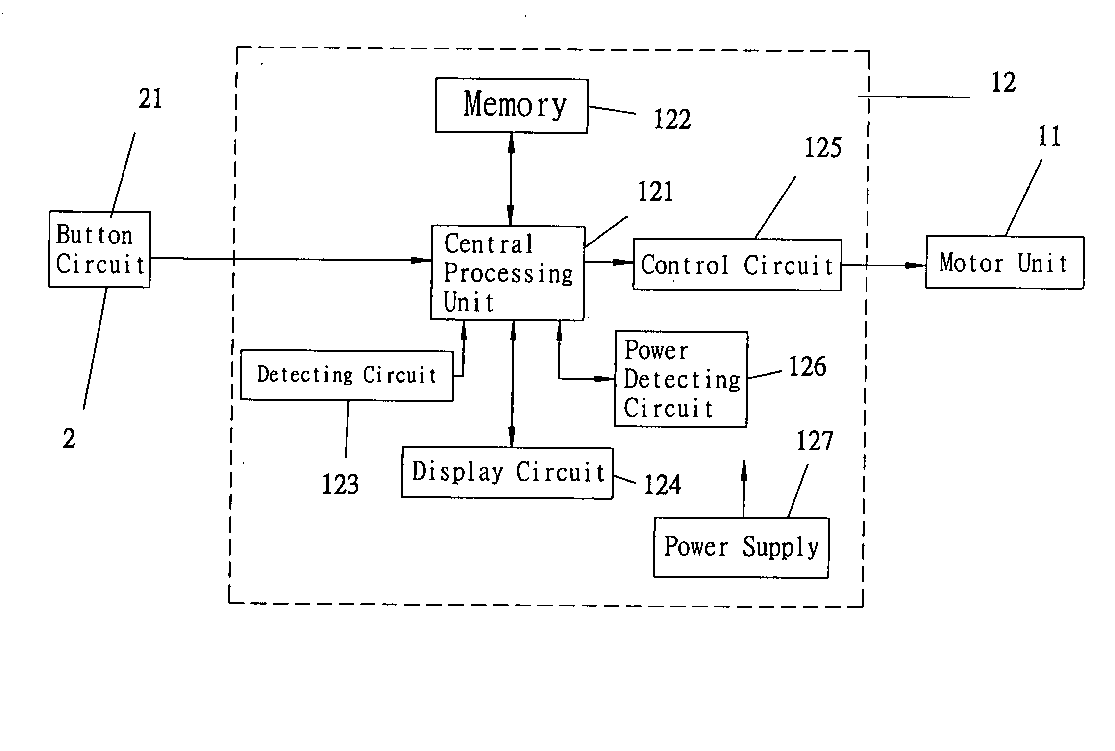
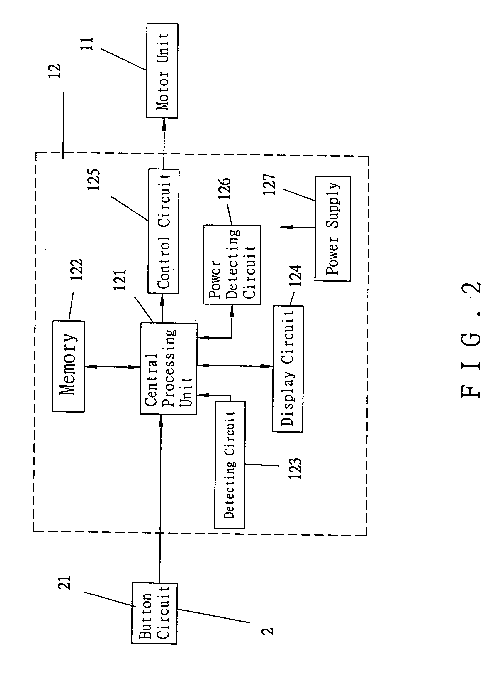
"The present invention provides a positioning / adjusting device for an outreaching / retracting member. The device includes a main unit and a controlling device. The main unit has a motor and a circuit assembly with a central processing unit, memory, a detecting circuit, and a control circuit. The detecting circuit detects the number of turns of a rotating disc, which is driven by the motor. The central processing unit stores the data of the number of turns of the motor in memory, providing a basis for the closed and open positions of the outreaching / retracting member. The controlling device has a button circuit with multiple buttons that send signals to the central processing unit to control the motor. The device allows for easy adjustment of the outreaching / retracting member's position."

Problems solved by technology

Adjustment of the positions of the first and second sliding blocks 22′ and 23′ was troublesome and time-consuming.
Namely, accurate adjustment was not possible and the adjusting procedure is inconvenient.

Method used


Image

  • Positioning/adjusting device for a shielding member
  • Positioning/adjusting device for a shielding member
  • Positioning/adjusting device for a shielding member

Examples


Embodiment Construction

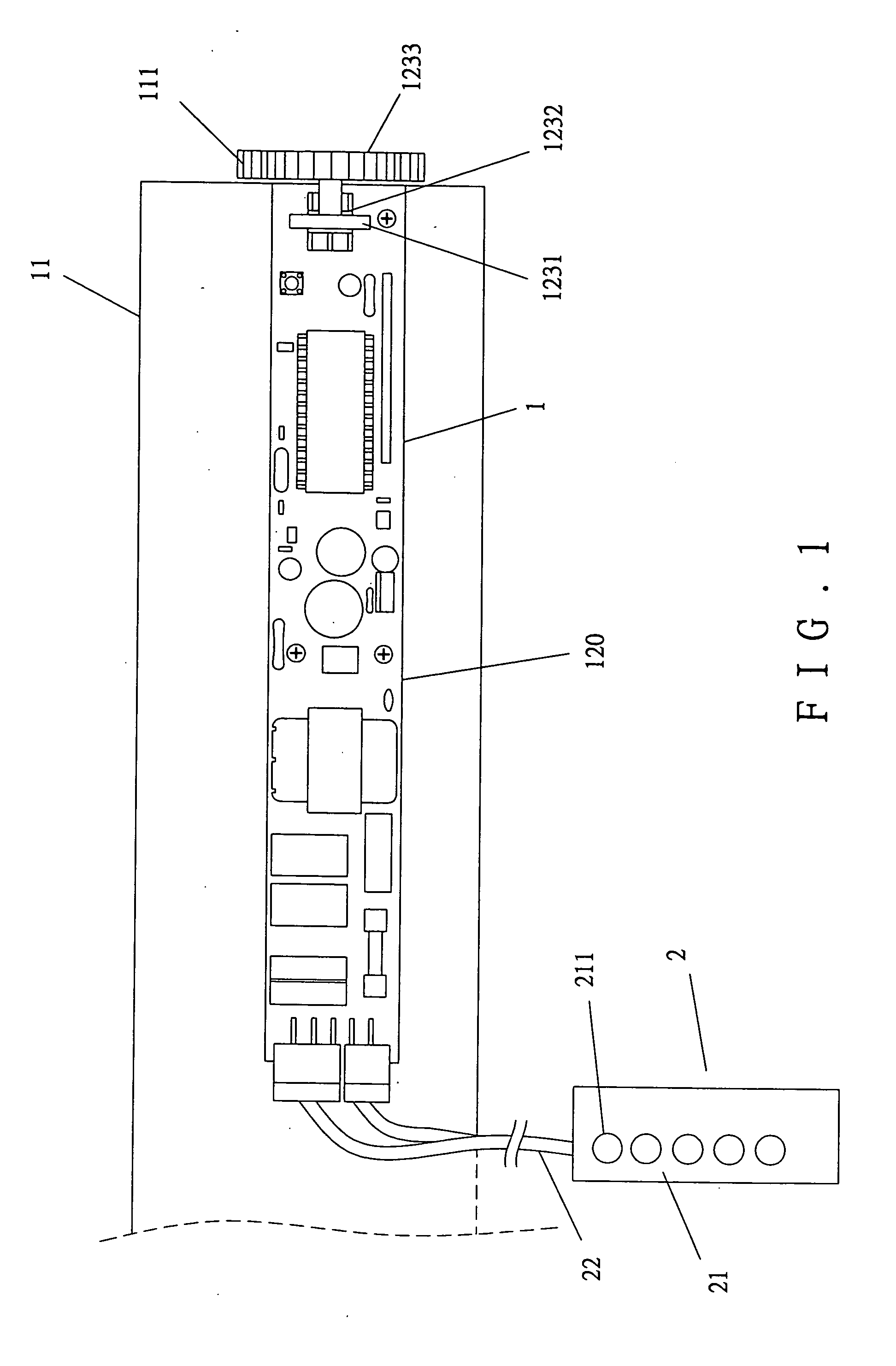
[0021] Referring to FIGS. 1 and 2, a positioning / adjusting device in accordance with the present invention generally comprises a main unit 1 and a controlling device 2 for controlling the main unit 1. The main unit 1 is engaged with an outreaching / retracting member that can be moved in an outreaching direction or a retracting direction. The outreaching / retracting member is a shielding member such as a coilable plate-like member (such as a rolling door), a plate with a fixed length, or a collapsible door.

[0022] In this embodiment, the main unit 1 includes a motor unit 11 and a circuit assembly 12. The main unit 1 can be fixed to a wall or any fixed object. The motor unit 11 includes a motor (not labeled) and a gear train (not labeled) for driving a drive gear 111, which, in turn, actuates the outreaching / retracting member.

[0023] The circuit assembly 12 includes a circuit board 120 on which a central processing unit 121, a memory 122, a detecting circuit 123, a display circuit 124, ...


PUM


Abstract

A positioning / adjusting device includes a main unit and a controlling device. The main unit includes a motor unit and a circuit assembly. The motor unit includes a motor for moving the outreaching / retracting member. The circuit assembly includes a detecting circuit for detecting turns of a disc driven by the motor unit. The data regarding the turns are sent to a central processing unit and stored in a memory. The central processing unit sends signals to a control circuit to control clockwise or counterclockwise rotation or stopping of the motor unit. The controlling device includes a button circuit, wherein when one of several buttons of the button circuit is pushed, a corresponding signal is sent to the central processing unit to thereby control clockwise or counterclockwise rotation or stopping of the motor unit and to thereby setting an uppermost position and a lowermost position of the outreaching / retracting member.

Description

BACKGROUND OF THE INVENTION [0001] 1. Field of the Invention [0002] The present invention relates to a positioning / adjusting device for an outreaching / retracting such as an electric rolling door. [0003] 2. Description of the Related Art [0004] It is usual to provide an electrically activated member such as an electric rolling door, an electric sliding door, an electric door curtain, or an electric venetian blind to shield the door or window of a house. Another electrically activated member includes a projection screen that is coiled up when not in use. [0005]FIG. 5 of the drawings illustrates an outreaching / retracting device for an electrically activated member. The device includes an outreaching / retracting member 11′ (e.g., a rolling door), a motor 12′ for driving the outreaching / retracting member 11′, a controller 13′ for controlling the turning direction of the motor 12′, and a positioning / adjusting device 2′ for adjusting a positioning point for the outreaching / retracting member...

Claims


Application Information

Patent Timeline
Patent Type & Authority Applications(United States)
IPC IPC(8): E05F15/10E06B9/68G05B1/06
CPCE06B9/68E06B2009/689E06B2009/6872
Inventor LEE, PAO CHEN
Owner LEE PAO CHEN
Learn More