Direct fuel injection engine

a fuel injection engine and direct technology, applied in combustion engines, machines/engines, pistons, etc., can solve the problems of difficult orientation of the fuel injection valve, deformation of the fuel-air mixture, and deformation of the stability of combustion, and achieve the effect of stable stratified combustion

Inactive Publication Date: 2005-05-12
NISSAN MOTOR CO LTD
View PDF4 Cites 13 Cited by
  • Summary
  • Abstract
  • Description
  • Claims
  • Application Information

AI Technical Summary

Benefits of technology

[0012] Another object of the present invention is to provide a direct fuel injection engine in which the fuel injection valve (injector) is slanted with respect to the center axis of the cylinder such that the engine can perform stable stratified combustion over a wide range of loads.

Problems solved by technology

It has been discovered that when the fuel injection valve is arranged at or near the center of the combustion chamber, it is sometimes difficult to orient the fuel injection valve such that it is parallel with the center reciprocation axis of the piston, i.e., such that the fuel injection valve is perpendicular to the top surface of the piston.
This spillage of the fuel stream from the deep cavity causes the stratification of the fuel-air mixture to deteriorate, the stability of the combustion to degrade, and unburned hydrocarbons to be exhausted from the engine.
Additionally, when the fuel stream spills out of the shallow recesses provided around the outside perimeter of the deep cavity, there is the risk that the fuel stream will reach the cylinder wall and cause hydrocarbon emission to increase.

Method used


Image

  • Direct fuel injection engine
  • Direct fuel injection engine
  • Direct fuel injection engine

Examples


first embodiment

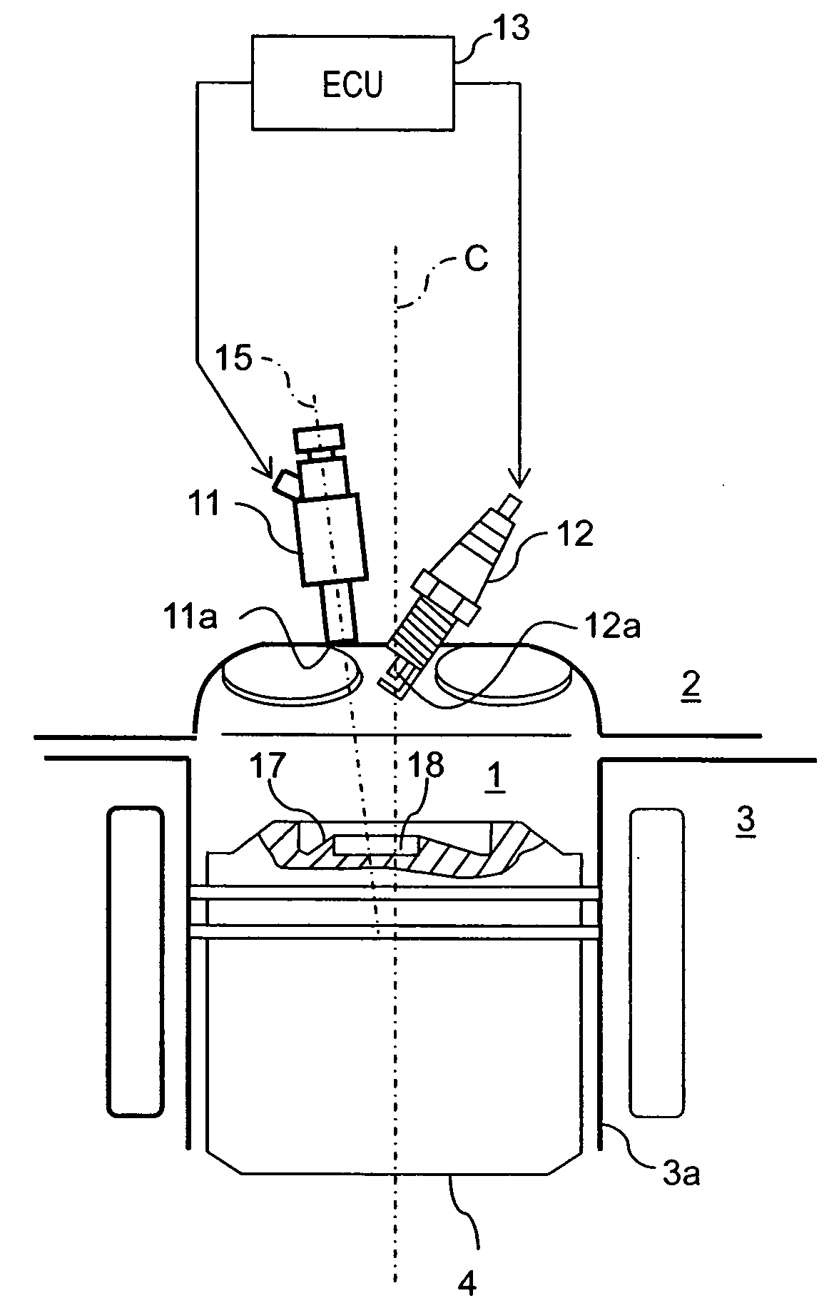
[0031] Referring initially to FIGS. 1 and 2, a direct fuel injection internal combustion engine (hereinafter “direct fuel injection engine”) is schematically illustrated in accordance with a first embodiment of the present invention. The direct fuel injection engine is a spark ignition internal combustion engine with direct fuel injection. FIGS. 1 and 2 are schematic partial cross-sectional views of an injection portion of the direct fuel injection engine of the first embodiment. As seen in FIGS. 1 and 2, the injection portion of the direct fuel injection engine includes a combustion chamber 1, a cylinder head 2, a cylinder block 3 with a cylinder 3a, a piston 4, a pair of intake ports 5, a pair of exhaust ports 6, a pair of intake valves 7, a pair of exhaust valves 8, an intake cam 9, an exhaust cam 10, a fuel injection valve or injector 11, a spark plug 12, and an engine control unit 13.

[0032] The combustion chamber 1 is basically defined by the cylinder head 2, the cylinder bloc...

second embodiment

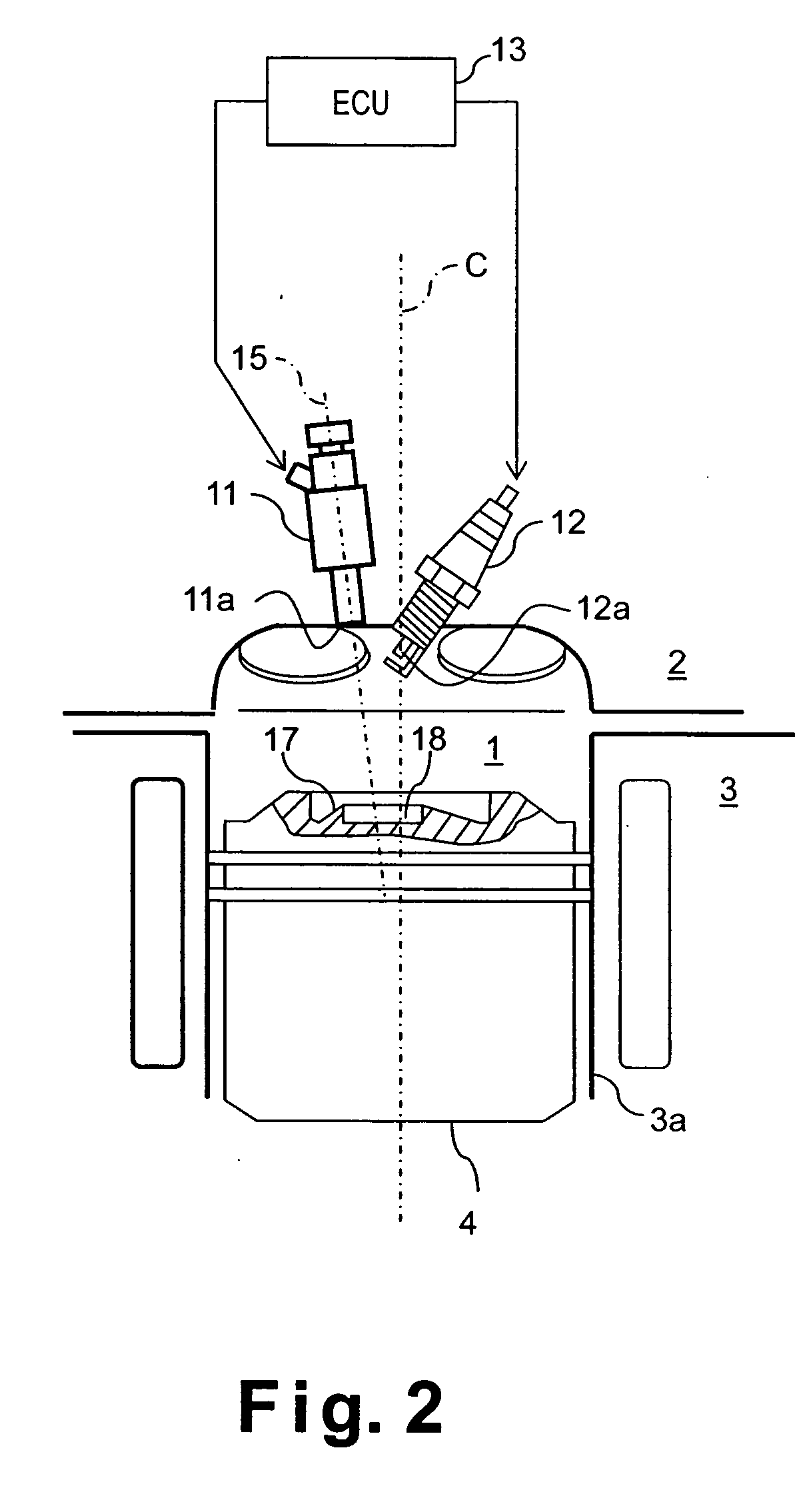
[0061] Referring initially to FIGS. 9 and 10, a direct fuel injection engine is schematically illustrated in accordance with a second embodiment of the present invention. In view of the similarity between the first and second embodiments, the parts of the second embodiment that are identical to the parts of the first embodiment will be given the same reference numerals as the parts of the first embodiment. Moreover, the descriptions of the parts of the second embodiment that are identical to the parts of the first embodiment may be omitted for the sake of brevity.

[0062] In this second embodiment, the positions of fuel injection valve 11 and the outer and inner cavities 17 and 18 have been changed. With this second embodiment of the present invention, the outer and inner cavities 17 and 18 are positioned such that the fuel stream does not spill out when the inner or outer cavity 17 or 18 is used to form a stratified fuel-air mixture. As a result, an appropriate stratified fuel-air m...


PUM


Abstract

A direct fuel injection engine is provided that an appropriate stratified fuel-air mixture is formed to conduct good stratified combustion over a wide range of loads. The engine has a fuel injection valve that is arranged at an upper surface of the combustion chamber on or near the center reciprocation axis of the piston and oriented such that the injection center axis of the fuel stream injected therefrom is slanted with respect to the center reciprocation axis of the piston. The piston is disposed in the combustion chamber to move along a cylinder center axis. The piston has a top surface having a first outer cavity having a first cavity center axis, and a second inner cavity located in the outer cavity. The second inner cavity has a second cavity center axis offset from the cylinder center axis of the piston in a direction perpendicular to the cylinder center axis.

Description

BACKGROUND OF THE INVENTION [0001] 1. Field of the Invention [0002] The present invention generally relates to a direct fuel injection engine in which a fuel is directly injected in a combustion chamber and ignited by a spark plug. More specifically, the present invention relates to a direct fuel injection engine that has a piston with a pair of cavities that are arranged to receive the injected fuel at an angle relative to the piston axis for obtaining an excellent stratified fuel-air mixture. [0003] 2. Background Information [0004] Fuel consumption of an internal combustion engine can be greatly reduced, particularly in low to medium load regions, when the internal combustion engine is configured to inject fuel directly into the combustion chamber from a fuel injection valve and very lean combustion is conducted by forming a stratified fuel-air mixture inside the cylinder. In order for this kind of direction fuel injection engine to ignite and combust the fuel-air mixture in a sta...

Claims


Application Information

Patent Timeline
Patent Type & Authority Applications(United States)
IPC IPC(8): F02B17/00F02B23/10
CPCF02B17/005Y02T10/125F02B2023/103F02B23/101Y02T10/12
Inventor TSUCHIDA, HIROFUMIHIRAYA, KOJIHOTTA, ISAMUSHIRAISHI, TAISUKESHIINO, TOSHIKAZU
Owner NISSAN MOTOR CO LTD
Why Eureka
Try Eureka