Wheelchair wheel lock

a technology for wheelchairs and wheels, applied in the field of wheelchairs, can solve problems such as slippage, and achieve the effect of preventing inadvertent travel of the chair and increasing weakness in a particular hemispher

Inactive Publication Date: 2005-05-05
TANKSLEY KEITH A +1
View PDF5 Cites 1 Cited by
  • Summary
  • Abstract
  • Description
  • Claims
  • Application Information

AI Technical Summary

Benefits of technology

[0009] It is known to provide a wheelchair for transporting fully or partially disabled persons, having a frame, a seat and back supported on the frame, and at least two primary drive wheels. When the wheelchair is at rest, it is often desirable to lock the wheels thereof to prevent inadvertent travel of the chair, either with or without an occupant. For example, when the occupant is exiting or entering the chair, such as to or from a bed, movement of the wheelchair is preferably restricted to provide a secure platform for the user. Accordingly, in one aspect, the present invention provides a wheel locking assembly for substantially preventing rotation of a wheelchair wheel or tire about its axis. Advantageously, the wheel locking assembly of the invention allows the user to lock both wheels of the wheelchair from a single side of the chair, rather than requiring the user to access separate locking mechanisms on opposed sides of the chair as is necessary in conventional wheelchair wheel lock designs. It will be appreciated that this feature provides significant advantages for users having a increased weakness in a particular hemisphere of the body, such as is common for stroke victims.
[0011] Conventional wheelchair wheels include a ground-engaging portion, typically fabricated of a resilient material such as rubber. To be effective for their intended purpose, wheelchair wheel locks must contact this ground-engaging portion with sufficient force to prevent rotation of the wheel. This usually causes the wheel-contacting surface of the wheel-engaging member to partially indent the ground-engaging portion, thereby reducing the likelihood of rotation. However, with conventional wheelchair wheel locks there is still a possibility of slippage.

Problems solved by technology

However, with conventional wheelchair wheel locks there is still a possibility of slippage.

Method used


Image

  • Wheelchair wheel lock
  • Wheelchair wheel lock
  • Wheelchair wheel lock

Examples


Embodiment Construction

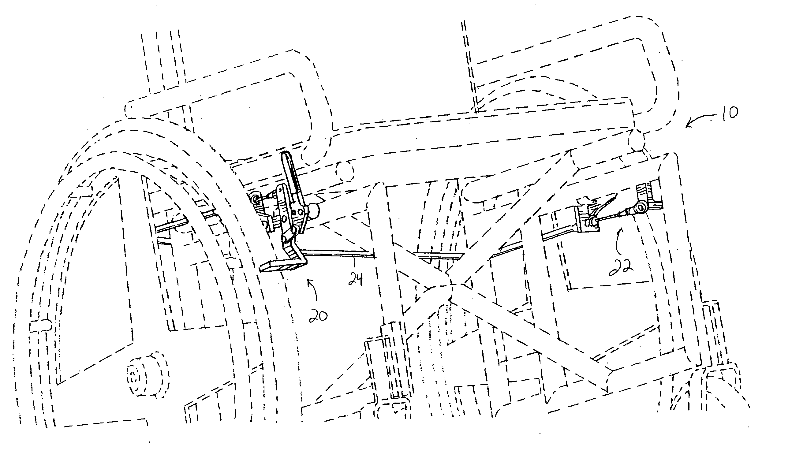
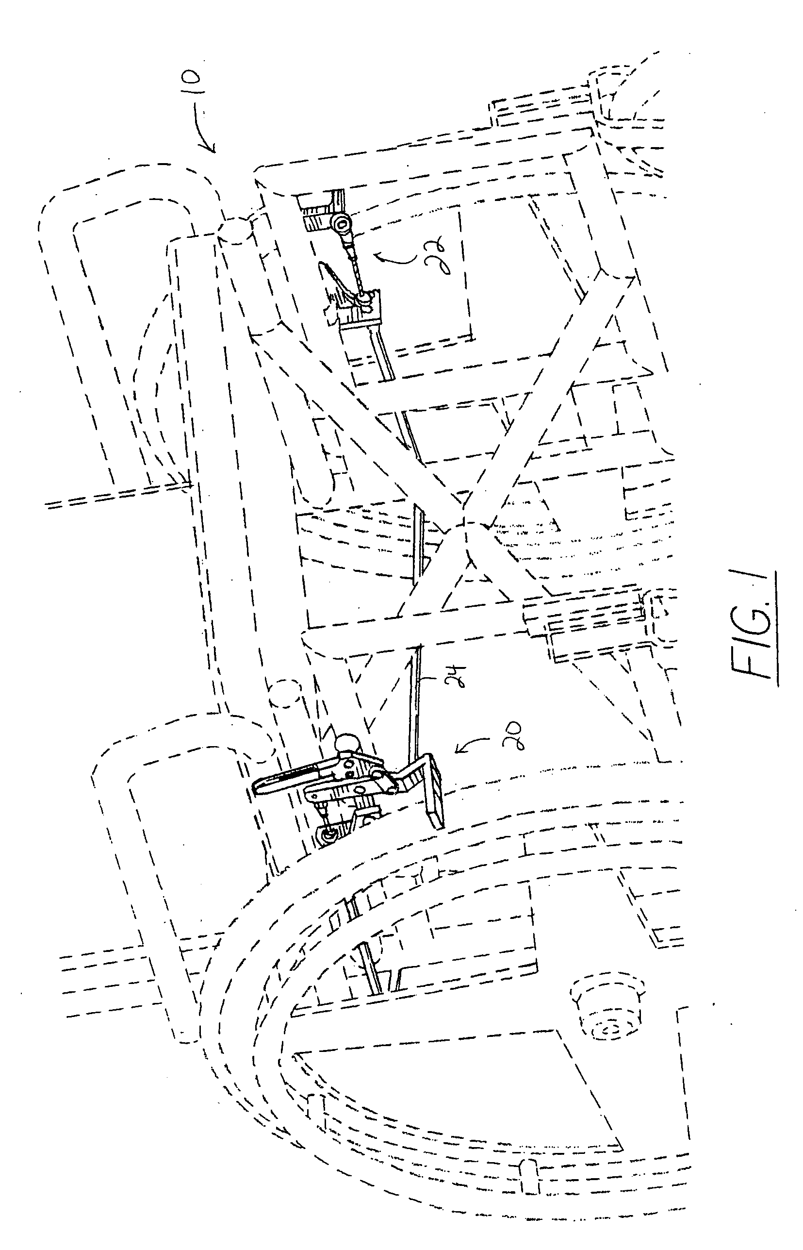
[0025] As best seen in FIG. 1 appended hereto, the wheel locking assembly 10 of the present invention may be mounted to a wheelchair (shown in broken lines for convenience) having a frame, a seat and back attached to the frame, and at least two primary drive wheels. Of course, the wheel locking assembly 10 of this invention will be mounted to the wheelchair such that the wheel locks are in spaced relation to the primary drive wheels to allow locking thereof. The wheel locking assembly 10 of the invention may comprise a first wheel stop 20, a second wheel stop 22, and a substantially continuously flexible linkage 24 operably connecting the wheel stops 20, 22. Wheel stops 20, 22 may be fabricated of any suitably durable, corrosion-resistant material commonly used to fabricate wheelchair wheel stops, including but not limited to metals such as aluminum and stainless steel, and suitably durable plastics

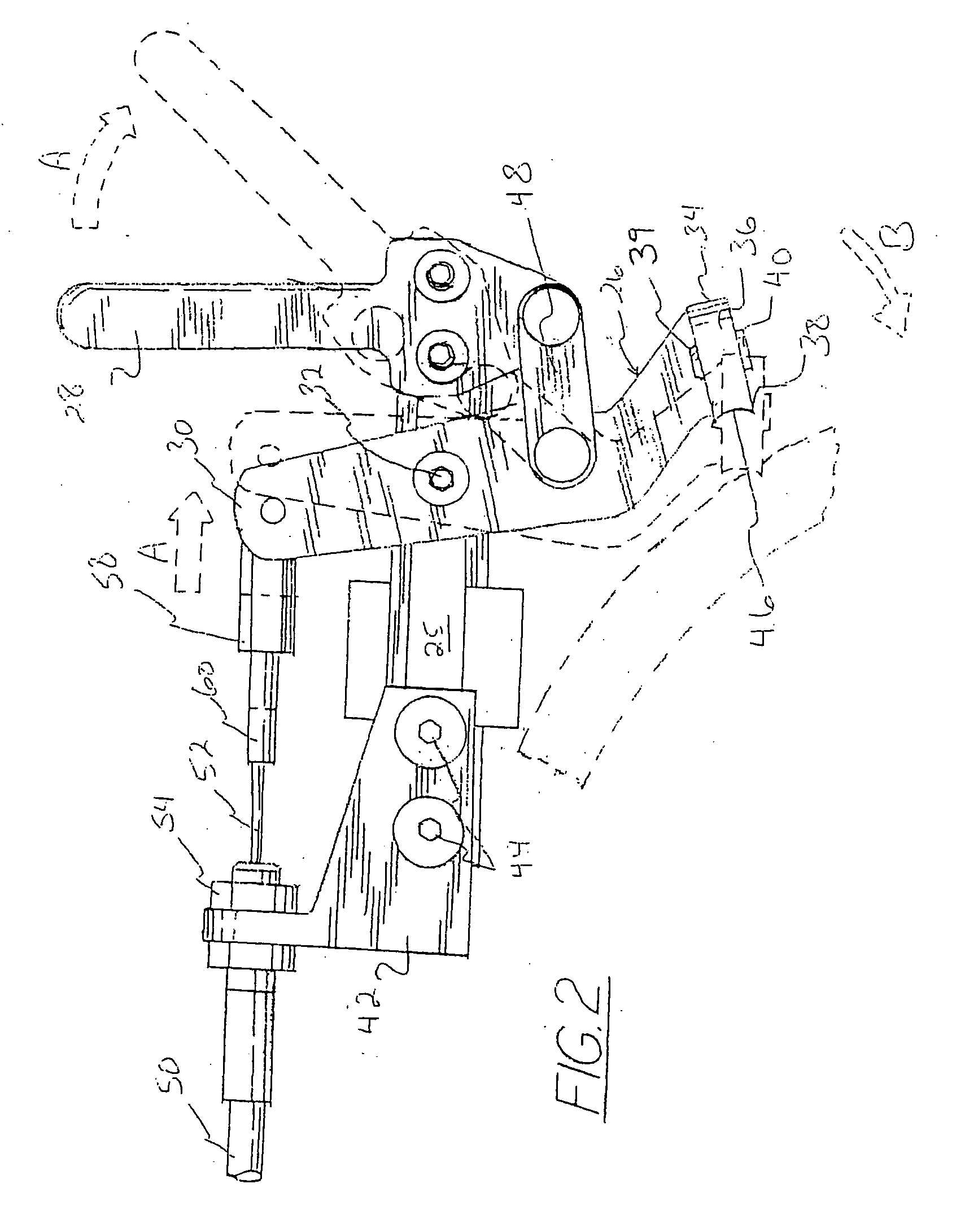
[0026]FIG. 4 is a perspective view of a dual-lever embodiment of the wheel locking a...


PUM


Abstract

A wheelchair wheel locking assembly comprises a first and a second displaceable wheel-engaging member, having a substantially continuously flexible linkage operably connecting the first and second wheel-engaging members. In the event the continuously flexible linkage is severed, the first wheel stop may continue to be operated by the actuating lever. A wheel-contacting surface of the wheel-engaging member may include a recess for engaging a portion of a wheel in an interference fit. A wheelchair comprising the wheel locking mechanism of the invention is also provided.

Description

[0001] This application claims the benefit of priority in U.S. Provisional Patent Application Ser. Nos. 60 / 344,612, filed Dec. 26, 2001, and 60 / 409,461, filed Sep. 10, 2002, both of which are incorporated herein by reference, and is a continuation of U.S. patent application Ser. No. 10 / 328,780, filed on Dec. 23, 2002, the entirety of which is also incorporated herein by reference.FIELD OF THE INVENTION [0002] This invention relates generally to the field of wheel locking mechanisms for wheelchairs. In particular, the present invention relates to a wheelchair lock adapted for use by individuals suffering from greater weakness in one hemisphere of the body. The present invention relates further to an improved wheel-contacting surface for a wheel lock, providing enhanced wheel locking power without necessitating use of additional force. BACKGROUND OF THE INVENTION [0003] It is known to provide wheelchairs with mechanisms for locking the wheels thereof, preventing the wheelchairs from t...

Claims


Application Information

Patent Timeline
Patent Type & Authority Applications(United States)
IPC IPC(8): B60T1/00B60T1/04
CPCB60T1/04B60T1/005
Inventor TANKSLEY, KEITH A.DONALDSON, BRUCE S.
Owner TANKSLEY KEITH A
Why Eureka
Try Eureka