
Tracking positions of personnel, vehicles, and inanimate objects

Active Publication Date: 2005-04-14
MERLIN TECH INC
View PDF19 Cites 110 Cited by
  • Summary
  • Abstract
  • Description
  • Claims
  • Application Information

AI Technical Summary

Benefits of technology

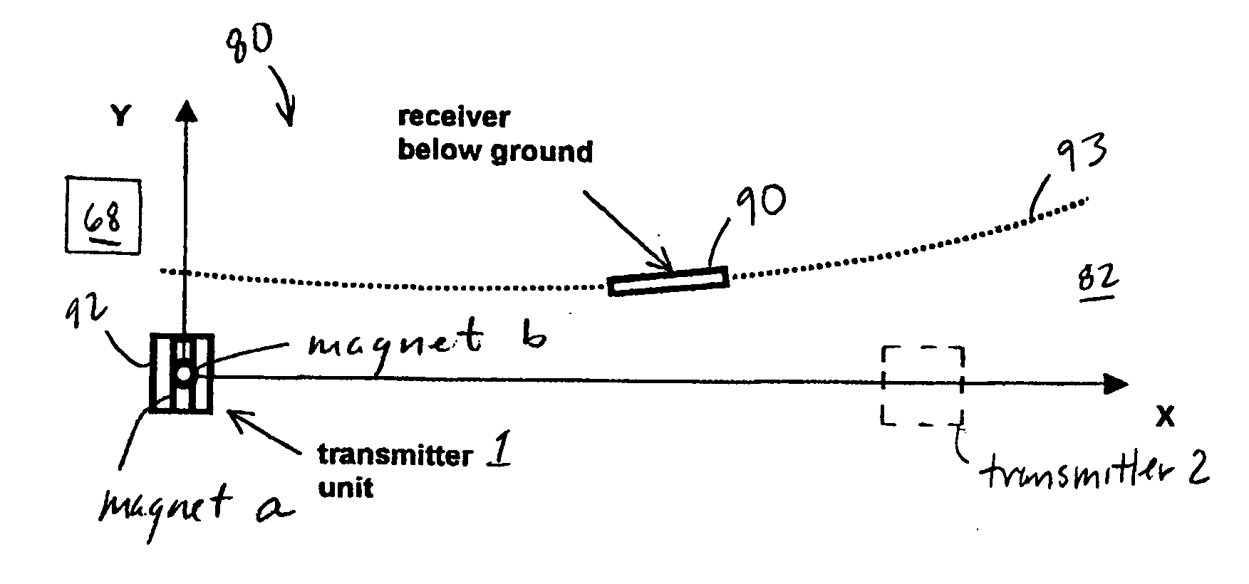
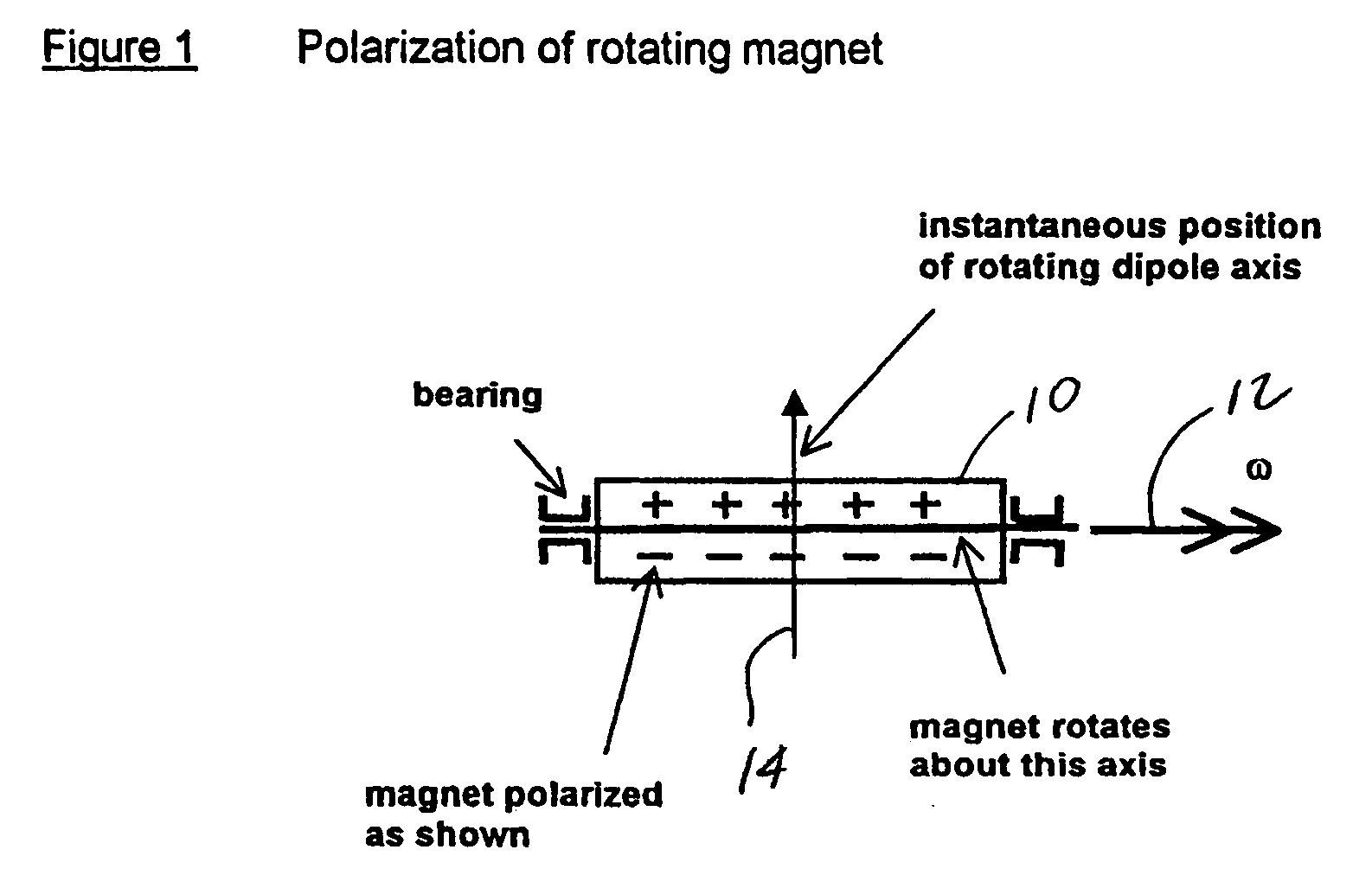
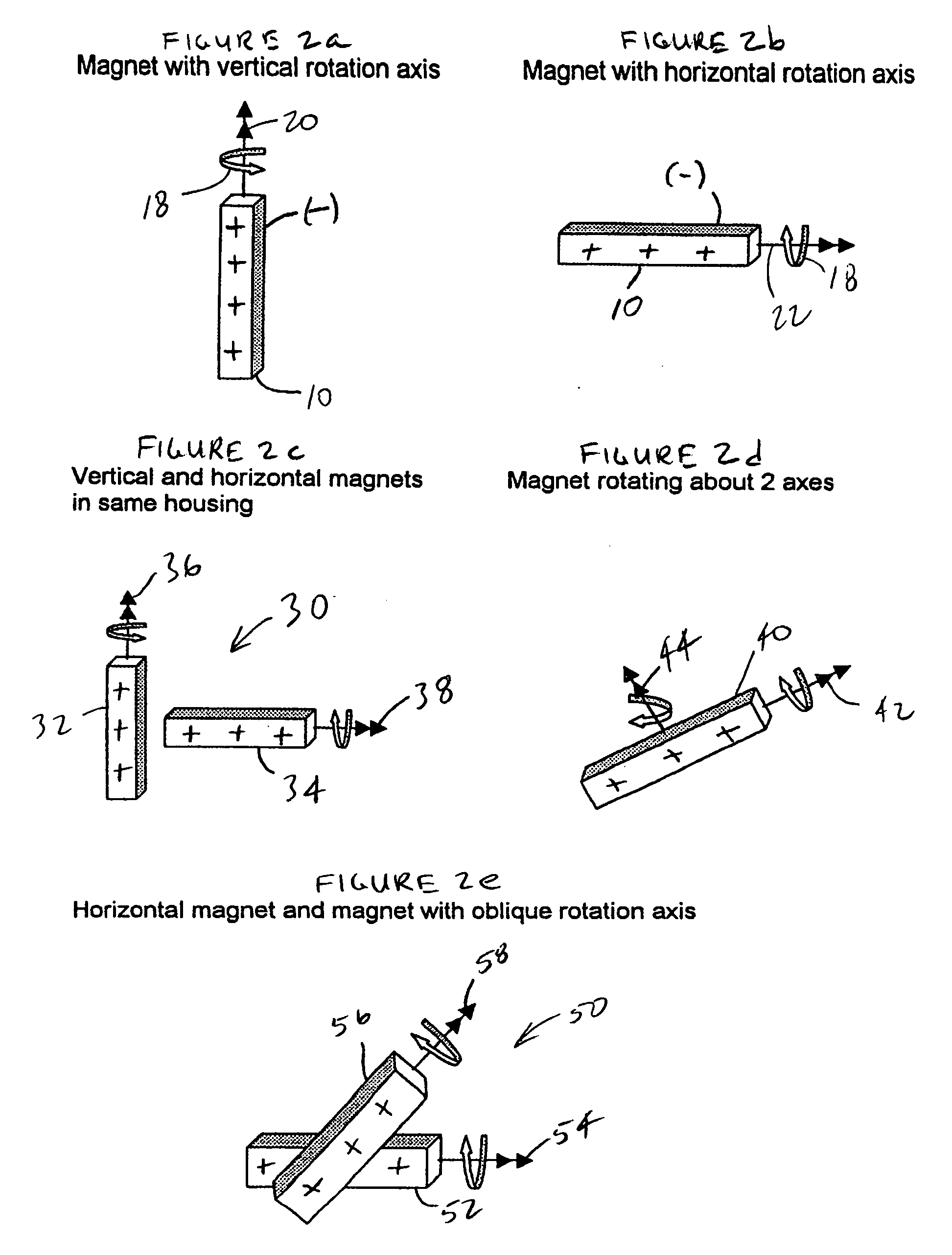
In one aspect of the present invention, in a system including a boring tool that is movable underground using a drill string which extends from the boring tool to a drill rig that operates at the surface of the ground, a portable device is configured for rotating a single, static magnetic field about an axis in a way which produces a rotating magnetic dipole field and for movement in relation to the surface of the ground by an operator. At least initially, a known elevational relationship is established between the portable device and the boring tool. The rotating magnetic dipole field is at least periodically sensed, starting in the known elevational relationship, and a receiver is used that is provided as part of the boring tool to at least periodically produce a receiver output responsive to the rotating dipole field. A positional relationship between the boring tool and the portable device is monitored by using the receiver output to establish at least a depth of the boring tool such that changing the positional relationship, by moving the portable device nearer to the boring tool, causes an increase in accuracy determination of the depth, as determined using the receiver output.

Problems solved by technology

A more limited number of prior art implementations make use of a dipole field wherein the dipole field axis is rotated about an axis that is generally perpendicular to the dipole field axis for purposes of monitoring position and / or orientation.
It is considered that this constraint markedly narrows the usefulness of the described method.
Unfortunately, this system does not appear to be capable of producing distance measurements.
Unfortunately, it appears that the techniques introduced by the Gilboa patents are limited at least with respect to their use of a plurality of detectors that are spaced apart from one another on the helmet in determining parameters associated with the helmet.
Further difficulties are introduced based on assumptions that the rotating magnet is fixed to the airframe of an aircraft in a known orientation and position and that the helmet position is at least approximately known with respect to the airframe and, therefore, with respect to the rotating magnet.
Such constraints may not be acceptable when the rotating magnet concept is applied in more general tracking and locating applications.

Method used


Image

  • Tracking positions of personnel, vehicles, and inanimate objects
  • Tracking positions of personnel, vehicles, and inanimate objects
  • Tracking positions of personnel, vehicles, and inanimate objects

Examples


Embodiment Construction

The following disclosure describes methods for tracking positions of people and objects with applications in the following areas:

Tracking of Personnel and Vehicles in Buildings

An important example of this kind resides in monitoring firefighters, police and medical aid personnel in buildings. A suitable tracking method should have sufficient range for accurate position monitoring across a large single story warehouse or diagonally across several floors of a multistory apartment or commercial building. Here, speed of equipment deployment is of utmost importance, leaving little time for calibration and other set-up tasks. Reliability is also an important design consideration.

Tracking positions of employees in large stores will improve customer service by more quickly dispatching needed personnel. For this application, ease of use and system reliability is more important than position accuracy and length of set-up time.

There is also much need to monitor positions of load carryin...


PUM


Abstract

A device rotates at least one static magnetic field about an axis, producing a rotating magnetic dipole field, and is movable in relation to the surface of the ground. The field is periodically sensed using a receiver to produce a receiver output responsive to the field. A positional relationship between the receiver and the device is monitored using the output. In one aspect, changing the positional relationship, by moving the device nearer to a boring tool which supports the receiver, causes an increase in accuracy of depth determination. In another aspect, determination of an actual overhead position of the boring tool, and its application, are described. Use of a plurality of measurements over at least one-half revolution of each magnet is disclosed. Establishing a surface radial direction toward a boring tool and resolution of multi-valued parameters is described. Calibration techniques, as well as a three transmitter configuration are also described.

Description

BACKGROUND OF THE INVENTION The present invention is related generally to the field of positional tracking using an electromagnetic field and, more particularly, to such tracking using a rotating dipole field. The prior art contains many examples of the use of an electromagnetic field for tracking and position monitoring purposes. A number of these prior art implementations specifically utilize an electromagnetic dipole field. In particular applications, such as, for example, horizontal directional drilling, a dipole field is particularly useful, at least in part, as a result of its axisymmetric field pattern. That is, the axis of the dipole field can be oriented along the axis of a rotating boring tool in order to create a quasistatic field. It is noted that the electromagnetic dipole field is advantageous with respect to the ability to modulate the field with information of interest. A more limited number of prior art implementations make use of a dipole field wherein the dipol...

Claims


Application Information

Patent Timeline
CPCG01V3/08E21B47/02224G01V3/081E21B47/0232G01V3/38G01D5/2006
Inventor ZELLER, RUDOLFBRUNE, GUENTER W.CHAU, ALBERT W.MERCER, JOHN E.
Owner MERLIN TECH INC
Learn More