
Device for hanging decorative fixtures

Inactive Publication Date: 2005-04-07
MORIN DENIS
View PDF25 Cites 1 Cited by
  • Summary
  • Abstract
  • Description
  • Claims
  • Application Information

AI Technical Summary

Benefits of technology

[0007] The above discussed and other drawbacks and deficiencies are overcome or alleviated by an apparatus and method device for mounting a cord on a gutter and similar hard to reach structures, including gutters and trees. The apparatus and method include a hanger clip having a cord retainer and a first bight configured to at least one of clip to two opposing substantially vertical surfaces defining the structure and suspend the hanger clip by the first bight; and an elongated staff for installing and removing the hanger clip. The elongated staff includes a lock feature disposed at one end of thereof to engage a corresponding mat

Problems solved by technology

The installation of these devices was particularly time consuming and laborious and removal was equally complicated.
In addition, these devices could not be rearranged at a later date to accommodate changes in the structure of the building or simply to rearrange for a different display of the lights.
Such hooks have many advantages in that they are relatively easy to use and remove but may still be difficult to install onto gutters and other building fixtures or hard to reach structures.
In practice, however, this solution requires a difficult and delicate operation to get the hook to seat properly on the wide variety of gutter lips found on houses, particularly when the desired mounting location is at a fairly high elevation (11 feet or more on many houses).
Moreover, use of the elongated staff is cumbersome, as there needs to be amble room and the staff long enough to pivot the staff at an end opposite the hook to properly position the hook with respect to the gutter lip extending horizontally from a leading edge defining the gutter toward the house.

Method used


Image

  • Device for hanging decorative fixtures
  • Device for hanging decorative fixtures
  • Device for hanging decorative fixtures

Examples


Embodiment Construction

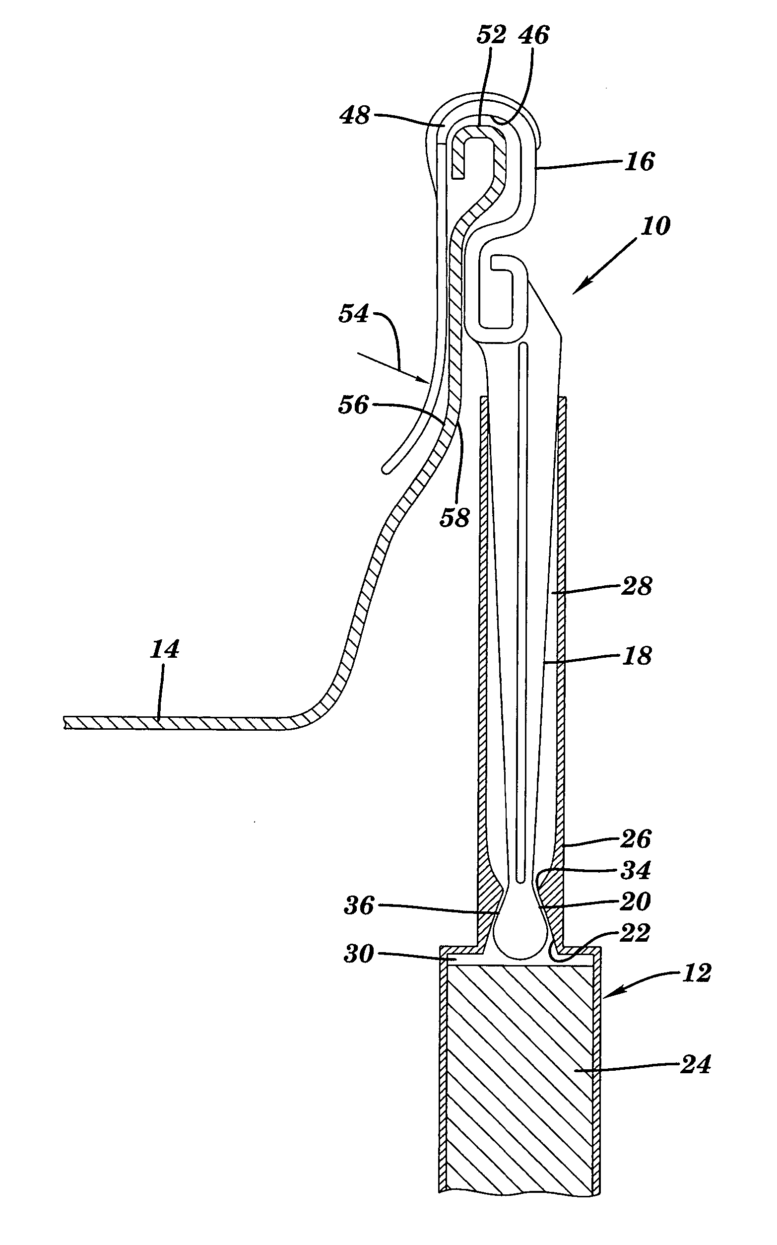
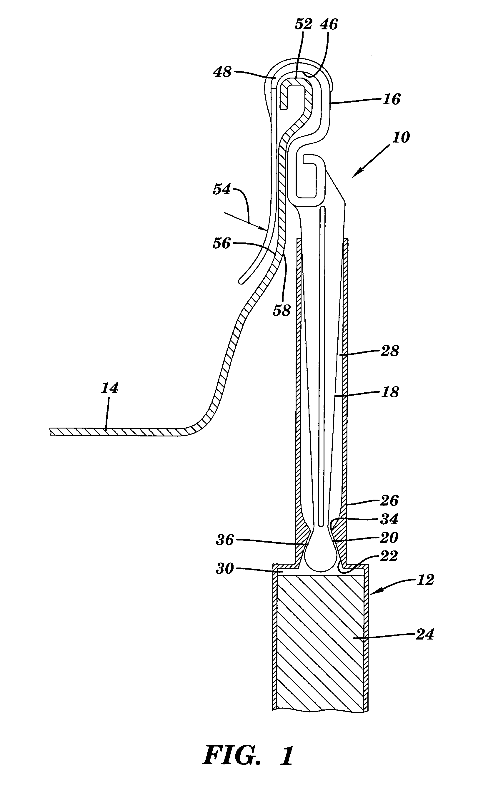
[0015] Referring to FIG. 1, there is shown a perspective view of a hanger clip and elongated staff. Although the present invention will be described with reference to the single embodiment shown in the drawings, it should be understood that the present invention can be embodied in many alternate forms or embodiments. In addition, any suitable size, shape or type of elements or materials could be used.

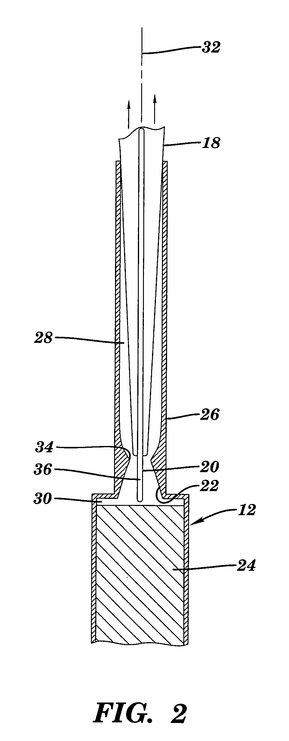
[0016]FIG. 1 illustrates a hanger clip 10 removably coupled to an elongated staff 12 for operably coupling clip 10 to a gutter 14. Hanger clip 10 includes a S-hook 16 and a member 18 extending therefrom and terminating at a lockable profile feature or lock feature 20. Lockable profile feature 20 engages a complimentary lock feature 22 configured in elongated staff 12 for preventing translation of clip 10 in a direction corresponding to an axis defining staff 12.

[0017] Elongated staff 12 includes an elongated rod 24 disposed in a hanger clip tool 26 defining one end of staff 12. Tool 2...


PUM


Abstract

System and method to easily install and remove hangers for a string of decorative lights around a house or a tree, while standing on the ground and without the use of a ladder. The system and method are particularly intended for attachment to gutter lips, but could be used to attach light strings to a variety of hard to reach surfaces found on and around buildings. The system is comprised of two components, a hanger clip which holds the light string and which is adapted to be suspended by a gutter or tree branch, for example, and an elongated staff configured at one end to temporarily hold the clip until it can be positioned and attached. The staff and hanger clip are engaged by corresponding locking means configured in each, to selectively and temporarily lock the hanger clip at a desired rotation angle relative to an axis defining the elongated staff. In an exemplary embodiment, the hanger clip is configured to simulate an icicle or ornamental object.

Description

BACKGROUND OF INVENTION [0001] The present invention relates to a method of installing and displaying decorative lights, such as a continuous strand of Christmas lights, around a house, while standing on the ground, and without the necessity of having to use a ladder. More specifically, the present invention relates to decorative simulated icicles for supporting ornamental lights that may be used during the holiday season. [0002] Decorative lighting fixtures are becoming more sophisticated with every new holiday season. Gone are the days when simple blinking lights strung around trees would suffice to welcome Christmas and the New Year. Today there is a demand for more sophisticated lighting scenarios to adorn homes and buildings. With the demand for new lighting arrangements comes the need for newer and improved flexible frames to support these lighting arrangements and attachment devices to affix such frames to buildings and other structures. [0003] In addition to the increasing d...

Claims


Application Information

Patent Timeline
IPC IPC(8): A47G33/08A47G33/10F21S4/00F21V21/088
CPCA47G33/0845F21V21/088F21S4/001A47G33/10F21S4/10
Inventor MORIN, DENIS
Owner MORIN DENIS
Learn More