Ribbon assembly for forming a decorative bow

Inactive Publication Date: 2005-04-07
CHENG KUI ENG
View PDF13 Cites 6 Cited by
  • Summary
  • Abstract
  • Description
  • Claims
  • Application Information

AI Technical Summary

Benefits of technology

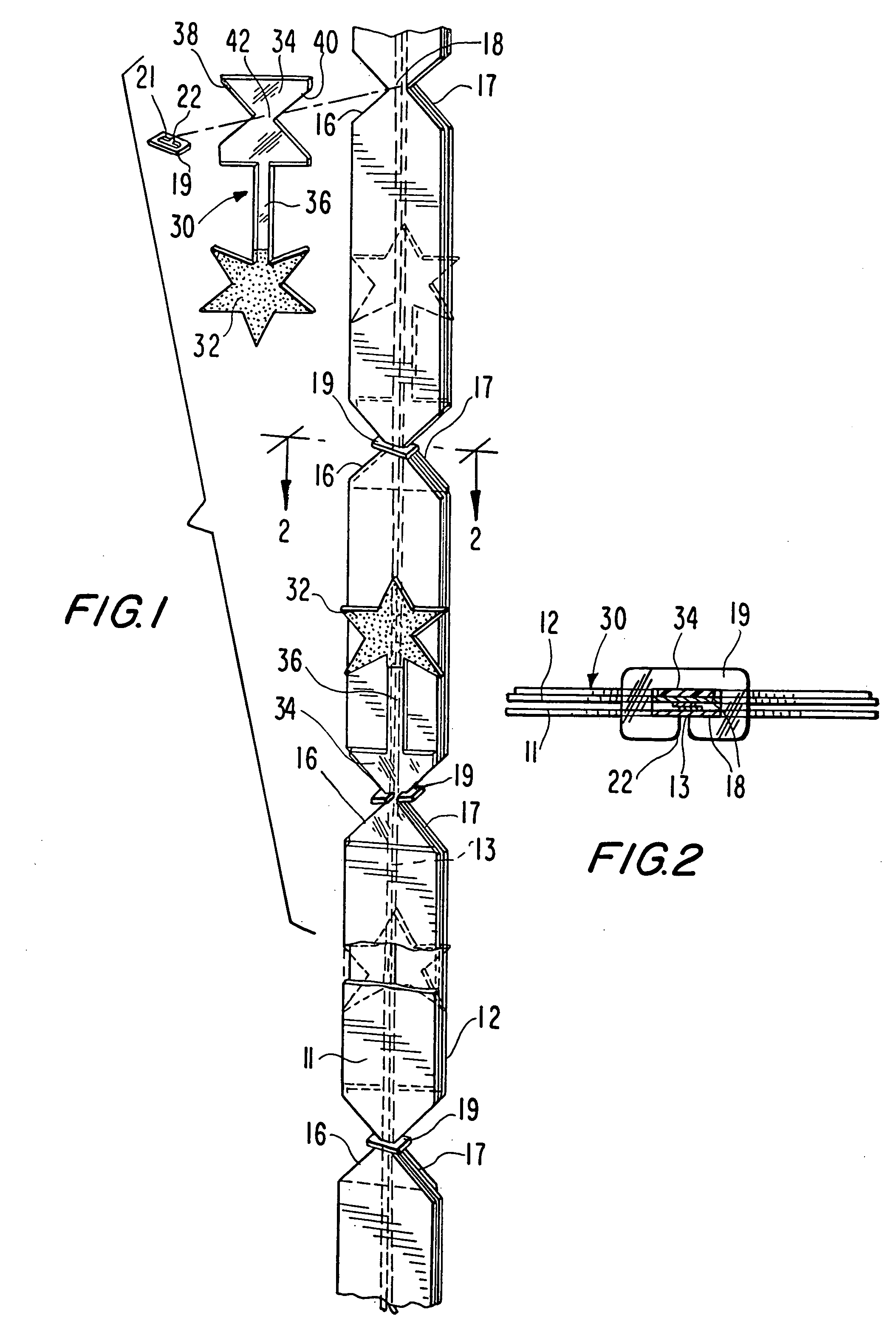
[0011] In keeping with these objects and others which will become apparent hereinafter, one feature of this invention resides, briefly stated, in a bow-forming ribbon assembly comprising at least one flexible ribbon member, and preferably a pair of juxtaposed ribbon members, and a plurality of relatively stiff retainer members mounted on, and spaced apart lengthwise along, the ribbon members. Each retainer member is restrained against movement relative to the ribbon members and defines an aperture extending generally transversely across the ribbon members at an angle with respect to the transverse direction. Each retainer member extends at an angle different from that of an adjacent retainer member. At least one drawstring member, and preferably a pair of drawstring members, is secured to one end of the ribbon member or ribbon members and runs freely through the apertures formed by the successive retainer members.
[0013] Each decorative arm has a decoration at its outer free end region. The decoration may be a star, a heart, or virtually any adornment. The decoration may even be, or include, any text, for example, the words “Happy Birthday”. The decorative arms for any one bow can include the same adornment, or different adornments, for even greater visual appeal.

Problems solved by technology

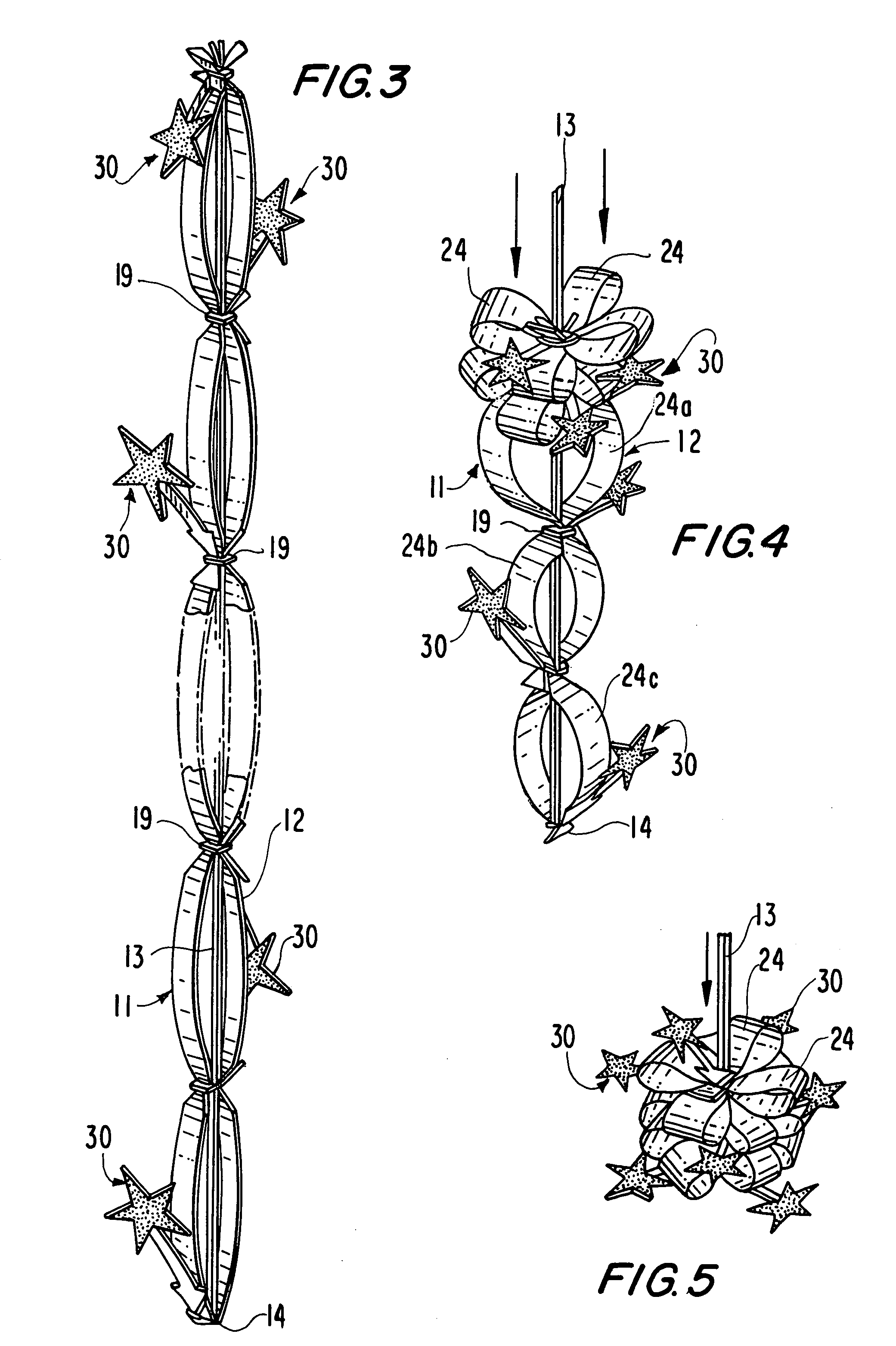
Prior ribbon assemblies, however, suffer from the disadvantage that, upon pulling the drawstring, the ribbon tends to fold itself into loops which are all aligned in one vertical plane, thus forming a fan shape.
This is inconvenient to the user who normally requires the bow to be arranged in a more decorative rosette or pom-pon form, and necessitates the user having to pull on the individual loops to rotate them laterally and rearrange them so that the loops are spaced angularly around a central vertical axis of the bow.
Apart from being time-consuming, this manipulation increases the risk of the bow becoming torn, damaged or soiled.

Method used


Image

  • Ribbon assembly for forming a decorative bow
  • Ribbon assembly for forming a decorative bow
  • Ribbon assembly for forming a decorative bow

Examples


Embodiment Construction

[0021] Referring to the drawings, FIG. 3 shows two elongated ribbon members 11 and 12 disposed in face-to-face relationship. The members 11 and 12 are formed by taking a length of conventional decorative ribbon material, e.g., a conventional synthetic plastic having a satin-like fibrous texture, and folding it at its middle portion 14. A drawstring 13, which may be formed of a narrower width of the same material as the members 11 and 12, is connected to the members 11 and 12, and passes between the two members 11 and 12. In the example illustrated, the drawstring 13 is a double length of material which is tied in a knot at its middle around the middle portion 14 of the folded-over ribbon members 11 and 12. Although in the example illustrated, the ribbon is formed from two ribbon members 11 and 12 and a double length of the drawstring material 13 is provided, as will be appreciated, the ribbon may instead comprise only a single length of the ribbon material 11, and only a single draw...


PUM


Abstract

A bow-forming ribbon assembly has a decorative flexible ribbon member and a drawstring connected loosely to the ribbon at points along its length by relatively stiff retainer members. Each retainer member extends generally transversely across the ribbon member, and each is inclined with respect to the transverse direction at an angle. Each retainer member is inclined at an angle different from that of an adjacent retainer member. Decorative arms having adornments are mounted adjacent at least some of the retainer members. On forming the ribbon into a bow by pulling the drawstring relative to the ribbon member, the inclined retainer members tend to skew the adjacent loops or segments of the bow relative to one another, as well as the decorative arms so that the loops and the arms are distributed at various angles around the axis of the bow, thereby providing a bow of great visual interest.

Description

BACKGROUND OF THE INVENTION [0001] 1. Field of the Invention [0002] The present invention relates to a ribbon assembly for forming a decorative bow, to be applied to wrapped gifts, for example. [0003] 2. Description of the Related Art [0004] It is known to provide a ribbon with a drawstring connected loosely to the ribbon at points along its length and secured to the ribbon at one end so that a user of the ribbon assembly can draw the ribbon into a number of arcuate loops by pulling on the drawstring. One advantage of this known assembly is that the ribbon assembly can be packed flat, thus greatly facilitating and reducing the costs of storage and transport of the ribbon assemblies as compared with preformed bows which are relatively bulky and need to be packed in crush-proof containers. [0005] Prior ribbon assemblies, however, suffer from the disadvantage that, upon pulling the drawstring, the ribbon tends to fold itself into loops which are all aligned in one vertical plane, thus ...

Claims


Application Information

Patent Timeline
IPC IPC(8): D04D7/10
CPCD04D7/10D04D7/105
Inventor CHENG, KUI ENG
Owner CHENG KUI ENG
Why Eureka
Try Eureka