
Measuring instrument

a technology of measuring instruments and tape measures, applied in the direction of instruments, mechanical measuring arrangements, distance measurement, etc., can solve the problems of inability to directly measure the required distance, the stability of the project is endangered, and the measurement process is complicated, so as to achieve the effect of faster and more accurate marking of i-beams

Inactive Publication Date: 2005-04-07
CAUDLE JAMES T
View PDF16 Cites 1 Cited by
  • Summary
  • Abstract
  • Description
  • Claims
  • Application Information

AI Technical Summary

Benefits of technology

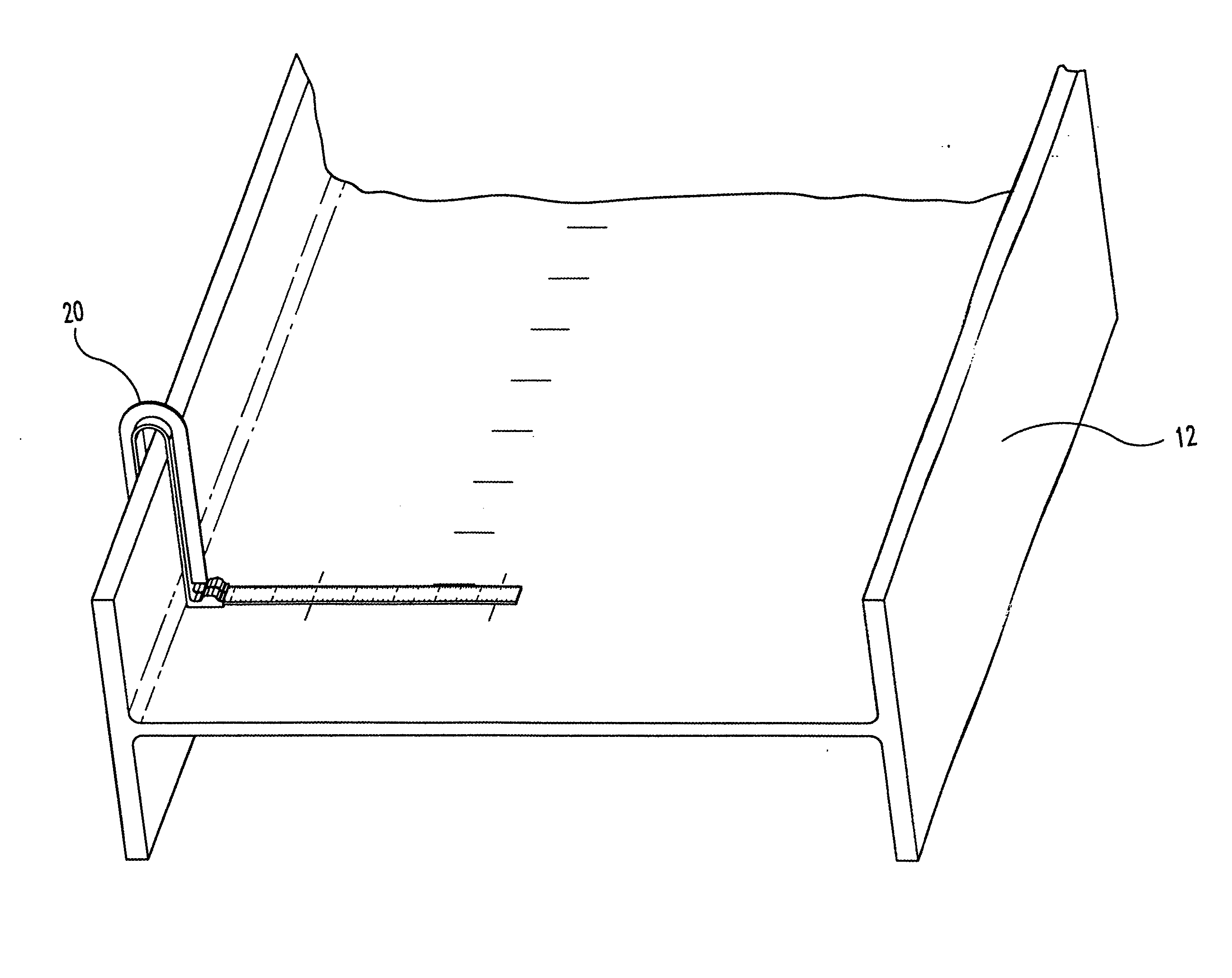
[0012] One object of the present invention is to provide a device for marking I-beams faster and more accurately that was possible using prior art tools and techniques.

Problems solved by technology

When the bolts are positioned even ⅛ of an inch off center, the stability of the project is endangered as the error is compounded over tens or hundreds of feet.
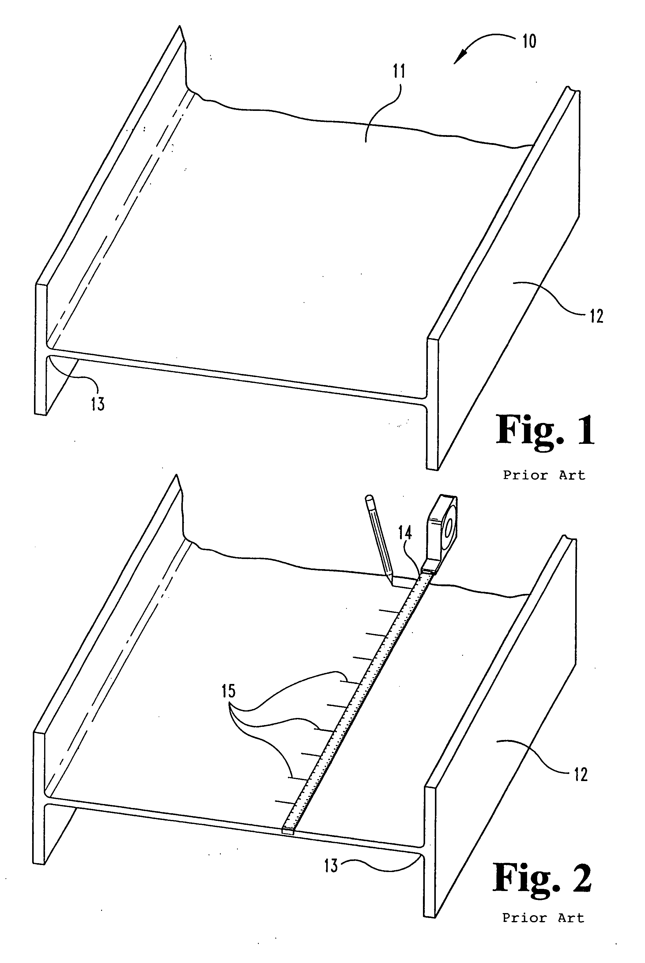
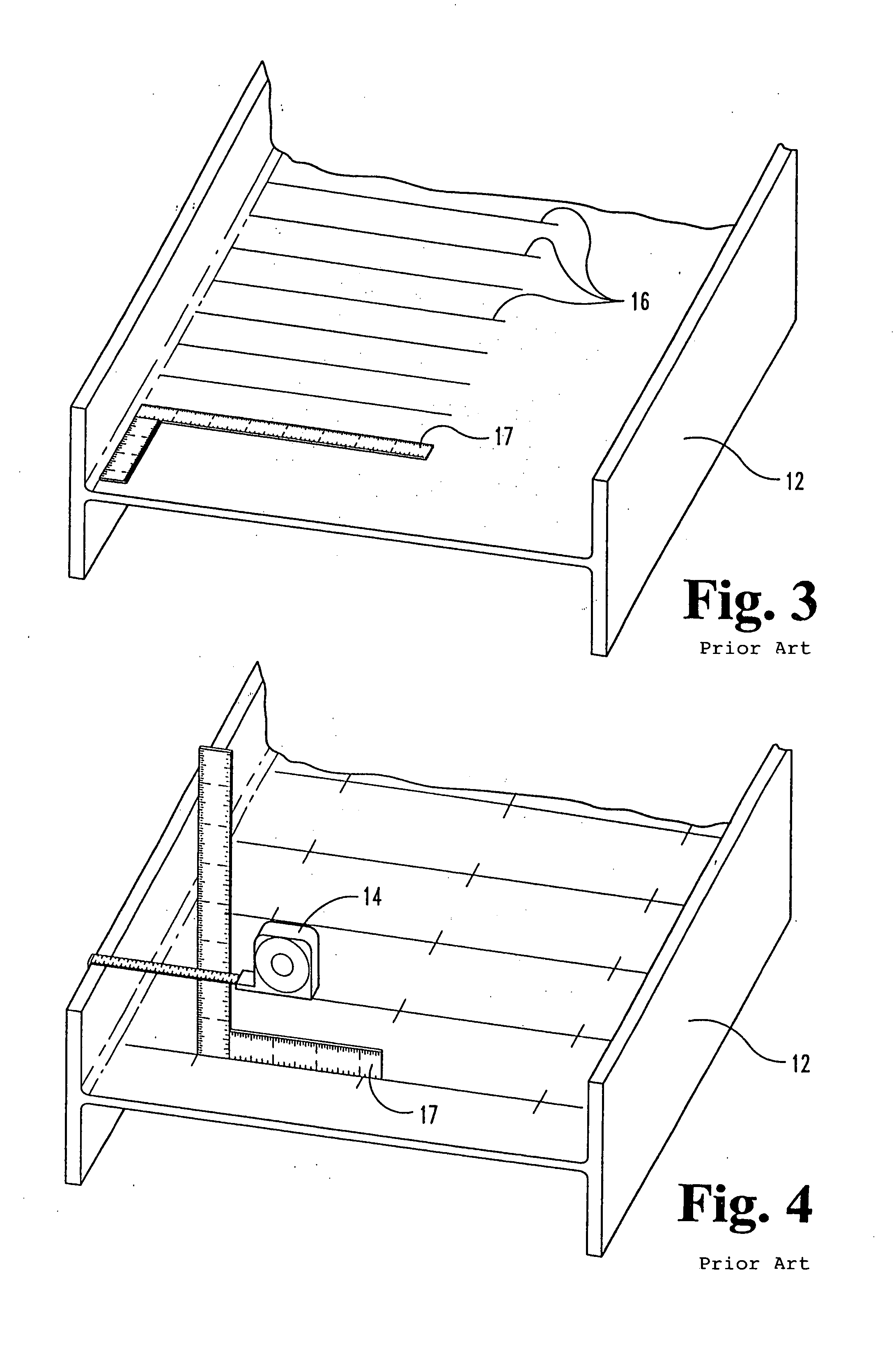
The measurement process is complicated by the fact that measurements are defined from the outside of the beam flange, while the hole itself is drilled in the beam web.
Thus, it is impossible to use a standard tape measure, for example, to measure the required distance directly.
This leads to errors in marking holes, since the method uses distances from the top of the flange as a guide.
In addition, the speed of the foregoing method is unsatisfactory since multiple tools and measurements are required for each point.

Method used


Image

  • Measuring instrument
  • Measuring instrument
  • Measuring instrument

Examples


Embodiment Construction

[0025] For the purposes of promoting an understanding of the principles of the invention, reference will now be made to certain preferred embodiments and specific language will be used to describe the same. It will nevertheless be understood that no limitation of the scope of the invention is thereby intended, such alterations and further modifications in the illustrated device, and such further applications of the principles of the invention as illustrated therein being contemplated as would normally occur to one skilled in the art to which the invention relates.

[0026] As indicated above, one aspect of the present invention relates to a device for measuring and marking lines and points in a steel I-beam. The preferred embodiment of the device comprises: (a) a flange-contacting portion for contacting the flange of an I-beam to be marked, and for defining a line parallel to the flange; (b) a measuring blade for measuring distances from the outside of the flange along the web of the ...


PUM


Abstract

A device for measuring and marking lines and points on a steel I-beam includes a rib for contacting the outside of an I-beam flange along a line opposite the center of the beam web, a measuring blade that rests on the beam web and measures distances from the outside of the flange, and a bridge for connecting the measuring blade to the rib in a way in which the measuring blade is held perpendicular to the flange. The device marks I-beams faster and more accurately that was possible using prior art tools and techniques.

Description

[0001] The present invention relates generally to measuring devices, and more particularly to a device for measuring and marking lines and points on steel I-beams. BACKGROUND OF THE INVENTION [0002] Steel I-beams are frequently used to build frameworks for large buildings and construction projects. The beams are connected together with bolts that must be positioned precisely given the large scale of the building. When the bolts are positioned even ⅛ of an inch off center, the stability of the project is endangered as the error is compounded over tens or hundreds of feet. [0003] The measurement process is complicated by the fact that measurements are defined from the outside of the beam flange, while the hole itself is drilled in the beam web. Thus, it is impossible to use a standard tape measure, for example, to measure the required distance directly. Instead, a square is generally used in combination with a tape measure, to make the appropriate measurement. [0004] More particularly...

Claims


Application Information

Patent Timeline
Patent Type & Authority Applications(United States)
IPC IPC(8): B25H7/00G01B3/00G01B5/00G01B5/04
CPCB25H7/00G01B5/04G01B5/0002G01B3/002
Inventor CAUDLE, JAMES T.
Owner CAUDLE JAMES T
Learn More