
Deflectable catheter assembly and method of making same

a technology of deflectable catheters and assemblies, which is applied in the direction of multi-lumen catheters, medical devices, other medical devices, etc., can solve the problems of increasing the amount of shaft torsional distortion (wind-up), and affecting the effect of force distribution

Active Publication Date: 2005-03-31
ABBOTT CARDIOVASCULAR
View PDF99 Cites 312 Cited by
  • Summary
  • Abstract
  • Description
  • Claims
  • Application Information

AI Technical Summary

Benefits of technology

[0010] There is a need for catheter assemblies that can compensate for the unbalanced moment and asymmetric stiffness in deflectable catheter assemblies. Many exemplary embodiments of this disclosure provide deflectable catheter assemblies with components that provide a balanced force distribution and a balanced moment.
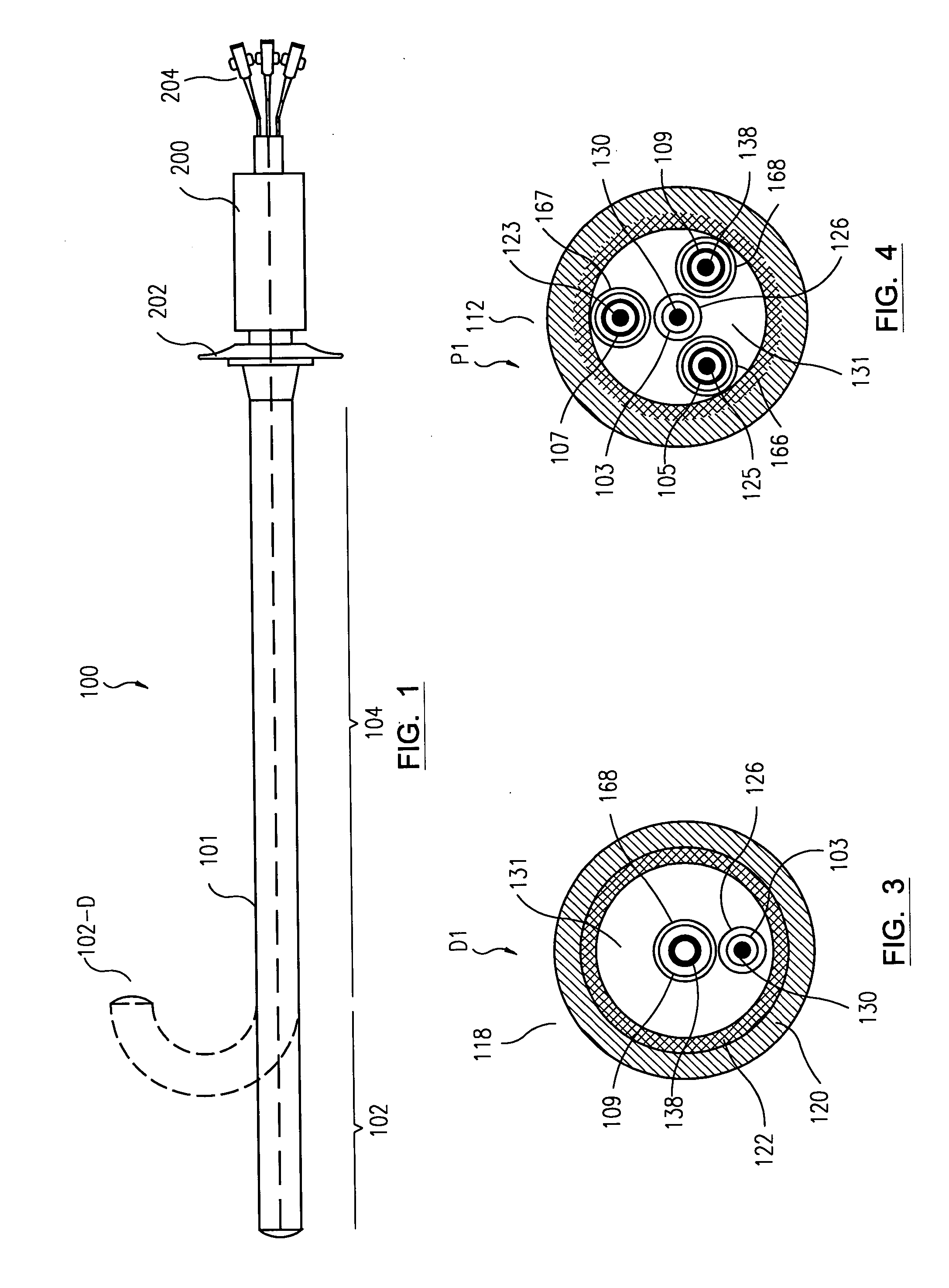
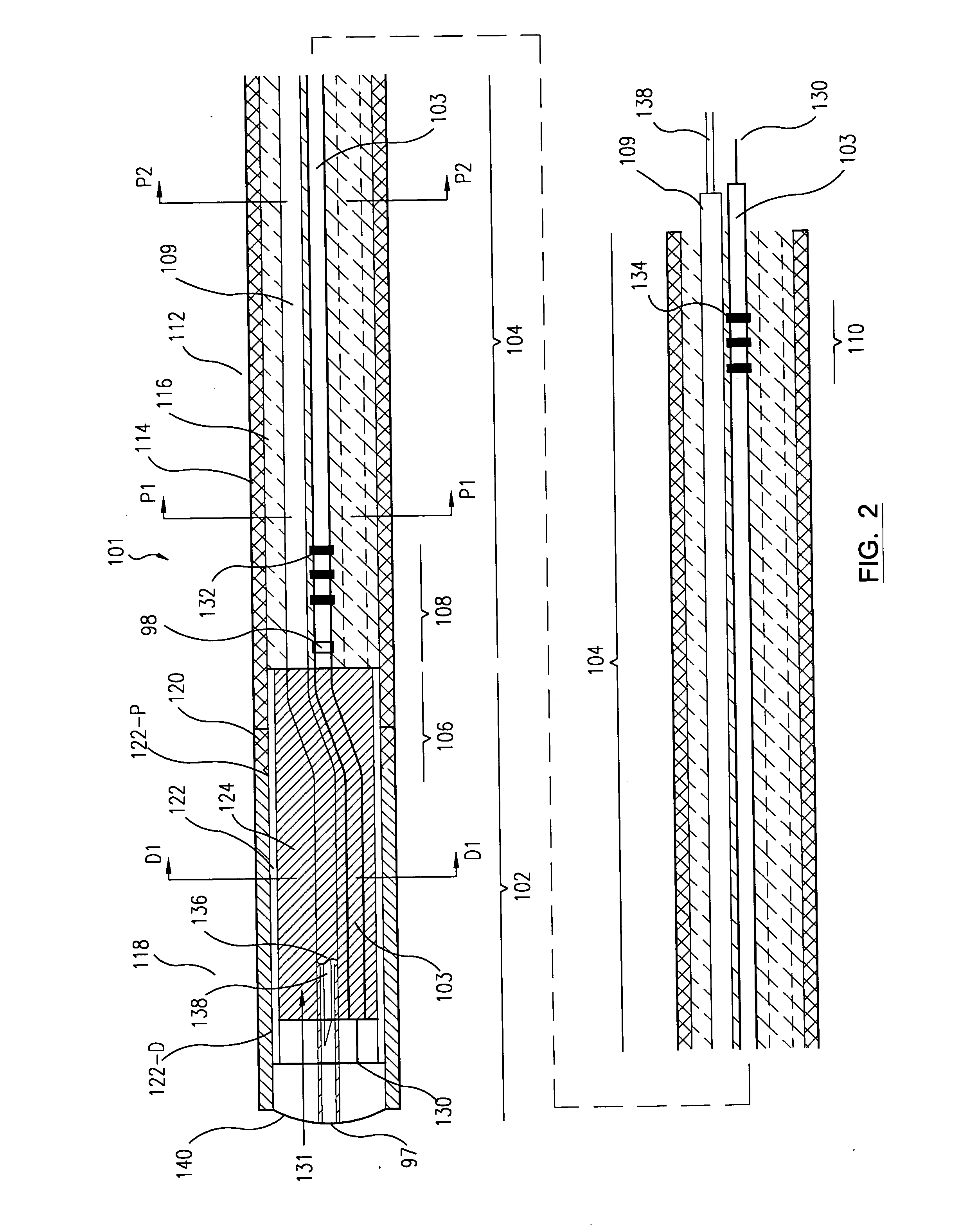
[0013] In an alternative embodiment, the tendon is wrapped around a needle to create a balance in the deflectable catheter assembly. Along the catheter distal section, the tendon is placed so that it is located off-center of the catheter shaft to allow defection of the catheter distal section and the tendon is not wrapped around the needle.
[0020] In an alternative embodiment, the deflectable catheter assembly includes a pressure transducer coupled to the needle to aid in monitoring the penetration depth of the needle.

Problems solved by technology

One problem commonly occurring in the working of this kind of catheter is that the catheter whips when rotated from the proximal end of the shaft.
Whipping is caused by the resistance of the catheter to turn away from its preferred orientation, which is generated by unbalanced stiffness over the cross-section of the catheter shaft.
This whipping problem gets further magnified when the catheter distal section is deflected and / or when the catheter is resident in tortuous vasculature.
If one tries to rotate the catheter shaft out of this preferred orientation, with the stiff section turning to the inside of the bending curve, the catheter shaft will resist this turning, requiring an applied torque in excess of that required if the catheter shaft had a balanced stiffness and resulting in an increased amount of shaft torsional distortion (wind-up) and accompanying stored torque in the catheter shaft.
In many cases, it is impossible to get the distal end of the catheter shaft to maintain an orientation in the vicinity of 180-degrees away from its preferred orientation with the rotation of the proximal end of the catheter shaft even if the proximal end of the catheter shaft is rotated in the opposite direction.
For an operator that only has control of the catheter's proximal end, whipping makes accurate control of the orientation of the catheter's distal end difficult, time consuming, and often very frustrating.
The whipping problem becomes more pronounced when the tendon is pulled to deflect the distal section.
The turning of the catheter shaft now has to work against not just the preferred orientation due to unbalanced stiffness but also against the compression load occurring preferentially on one side of the catheter shaft.

Method used


Image

  • Deflectable catheter assembly and method of making same
  • Deflectable catheter assembly and method of making same
  • Deflectable catheter assembly and method of making same

Examples


Embodiment Construction

[0067] Many aspects of this disclosure relate to a deflectable catheter assembly and methods of making and using such deflectable catheter assembly. For example, one aspect of this disclosure relates to a needle injection catheter assembly, for delivery of a biologic agent into the wall tissue of the heart, which includes an injection needle, a catheter shaft that includes a deflectable distal section, and a torque-transmitting shaft, and a proximal catheter handle. The catheter shaft is constructed in such a way that it balances moments and length variations commonly occurring in the operation of steerable catheters of this kind. This results in a catheter with superior rotation control and responses.

[0068] In the following description, for purposes of explanation, numerous specific details are set forth in order to provide a thorough understanding of the exemplary embodiments of the present invention. It will be evident, however, to one skilled in the art, that these embodiments ...


PUM


Abstract

A deflectable catheter assembly is disclosed. The assembly comprises a catheter shaft having a catheter proximal section and a catheter distal section, and at least one lumen extending therethrough. The catheter distal section is more flexible than the catheter proximal section. A tendon is disposed within a first lumen of said catheter shaft. The first lumen is approximately centrally located within the catheter shaft at the catheter proximal section. The first lumen is located off-center of the catheter shaft at the catheter distal section. The tendon is able to deflect the catheter distal section when being pulled on. A catheter handle is coupled to the catheter shaft at the catheter proximal section, the catheter handle includes a control mechanism to control the tendon.

Description

BACKGROUND [0001] 1. Field [0002] Many aspects of this disclosure relate to a deflectable catheter assembly and methods of making and using such deflectable catheter assembly. For example, the catheter assembly of an exemplary embodiment includes a deflectable distal section, a non-deflectable section, a proximal catheter handle, and a tool such as a needle, a therapeutic device, and a diagnostic device. [0003] 2. Discussion of Related Art [0004] Steerable catheters have been commonly used in applications such as mapping (e.g., cardiac mapping), drug delivery (e.g., intramyocardial drug delivery), and ablation, (e.g., arrhythmia ablation). [0005] A steerable catheter has a deflectable flexible distal section and a stiffer proximal torqueable shaft. The steerable function is accomplished by three modes of actions: 1) translational catheter movement along the shaft direction, 2) deflection of the distal deflectable section, and 3) turning of the catheter shaft to direct the deflection...

Claims


Application Information

Patent Timeline
IPC IPC(8): A61M25/00A61M25/01
CPCA61M25/0012A61M25/0013A61M25/005A61M25/0051A61M25/0054A61M25/0136A61M25/0138A61M25/0147A61M25/0152A61M2025/004A61M2025/0063A61M2025/0089A61M2025/009A61M2025/0096A61M2025/015A61M25/0029
Inventor CHOW, MINASTAMBERG, BARBARAWEBLER, WILLIAMSIMPSON, JOHNYAMBAO, AUGUSTASONGWE, GABRIELCHIU, JESSICALIU, LILIBEYERLEIN, DAGMAR
Owner ABBOTT CARDIOVASCULAR
Learn More