
Continuous safe suction device

Inactive Publication Date: 2005-03-24
KUNTZ CHARLES
View PDF15 Cites 84 Cited by
  • Summary
  • Abstract
  • Description
  • Claims
  • Application Information

AI Technical Summary

Benefits of technology

[0020] These and other features of the present invention will become readil

Problems solved by technology

Currently used mechanical drainage devices are subject to failure and / or human error and often harm, and potentially cause death to, the patient.
The patient is often harmed by draining fluid leaking back into the patient's body.
Another problem with the conventional drainage devices is that they are bulky and need to be plugged into electrical outlets or centralized wall-mounted suction hoses.
Finally, the conventional devices only allow monitoring of one patient at a time.

Method used


Image

  • Continuous safe suction device
  • Continuous safe suction device
  • Continuous safe suction device

Examples


embodiment 100

[0056] Referring to FIG. 9, there is shown an exploded view of the continuous safe suction device embodiment 100 showing suction storage member access cover 118, front cover 114, alphanumeric control keys 142, alphanumeric readout screen 140, computer and memory board 176 and spacer supports 178, liquid sensor 160, rear casing 116 having membrane suction storage member holder 148 and access cover screw receiver 184, membrane suction storage member 150, membrane holder ring 152 with membrane 188 and membrane resilience spring 192, battery access cover 143 with securing screw 145, and batteries 194 with battery to computer connectors 196.

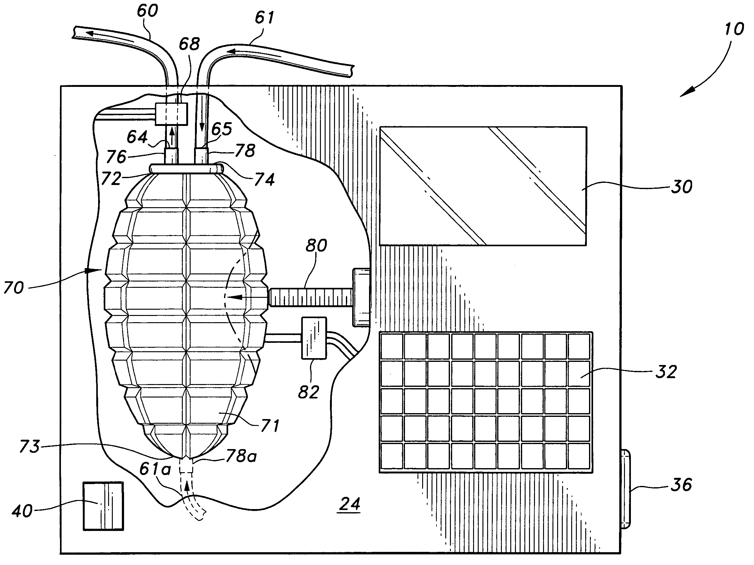
[0057] Referring to FIG. 10 there is a diagrammatic representation of the computer-controlled operation of the inventive bulb suction devices 10, 100. In the operation of the first embodiment 10, the sensor 82 senses when the bulb is fully extended and ready for emptying at which time it is sends a signal to the computer 90 which sends a signal to the...

embodiment 10

[0062] All the values of the readout screen 40 of the bulb suction embodiment 10 are available on readout screen 140, including piston position as a function of time during its incremental back-off stroke and its full extension-emptying stroke. Alarm values set by control keyboard panel 142 may be shown and monitored on readout screen 140 and the computer may activate alarm 200.

[0063] The liquid sensor is commercially available as model OPB350 from OPTECK Technology, inc., Carrolton, Tex.


PUM


Abstract

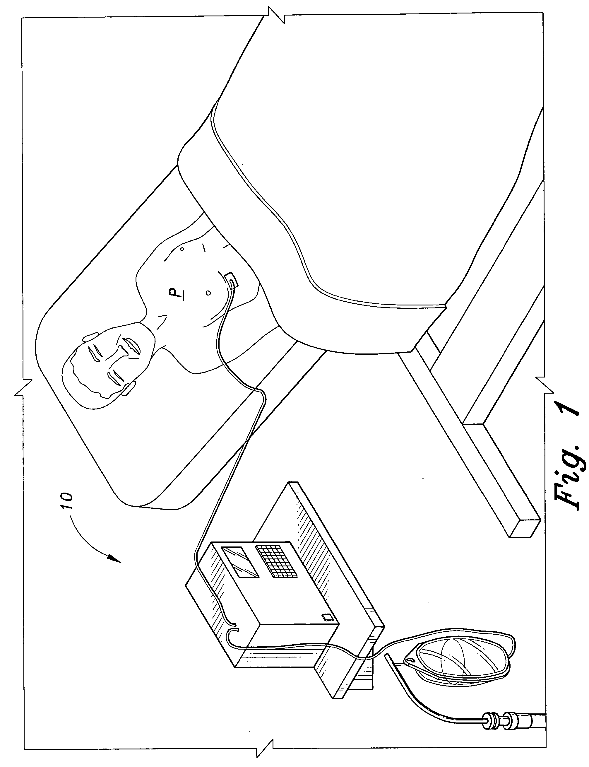
The continuous safe suction device safely removes fluids from a patient's body. The device has a housing for storing a suction-producing member. The suction-producing member is a collapsible bulb or, in another embodiment, a spring-loaded membrane and casing that when compressed, upon recoil will apply gentle suction to an input tube that drains fluid from the patient and transports it into the suction bulb or membrane and casing. The suction bulb or casing has a pair of one-way valves secured in-line with respective input and output tubes. Upon complete filling it is recompressed to force the fluid in the bulb out through the output tube, which transports the fluid to an exterior fluid collection bag. The suction bulb or casing is compressed by a screw piston, controlled by a sensor that determines when the bulb is filled and emptied, the screw piston, in one embodiment, being withdrawn incrementally.

Description

CROSS-REFERENCE TO RELATED APPLICATION [0001] This application claims the benefit of U.S. Provisional Patent Application Ser. No. 60 / 504,989, filed Sep. 23, 2003.BACKGROUND OF THE INVENTION [0002] 1. Field of the Invention [0003] The present invention relates to medical devices for draining fluids from a patient's body and, more particularly, to a continuous safe suction device using a suction bulb with one-way valves that prevent the drained fluid from flowing back to the patient. [0004] 2. Description of the Art [0005] There are many existing medical devices currently used for draining fluid from a patient's body. Body fluids are often transferred through tubes from the body of the patient to an exterior collection container for testing and storage. A suction device is often used to draw the body fluids through the transfer tubes. Several body fluid drainage devices have been developed. [0006] International Patent No. WO 90 / 07942, published on Jul. 26, 1990, discloses a method of ...

Claims


Application Information

Patent Timeline
IPC IPC(8): A61M1/00A61M37/00
CPCA61M1/0023A61M1/0066A61M1/0072A61M2205/3561A61M2205/3396A61M1/82A61M1/80A61M1/73
Inventor KUNTZ, CHARLES
Owner KUNTZ CHARLES
Learn More