
Electrical breast pump

a breast pump and electric technology, applied in the field of breast pump improvement, can solve the problems of reducing efficiency, pump not as efficient, and prior art pumps do not contemplate controlling the refractory time of the suction cycle, and achieve the effect of convenient engagemen

Active Publication Date: 2005-02-24
KELLY PATRICIA A +1
View PDF7 Cites 92 Cited by
  • Summary
  • Abstract
  • Description
  • Claims
  • Application Information

AI Technical Summary

Benefits of technology

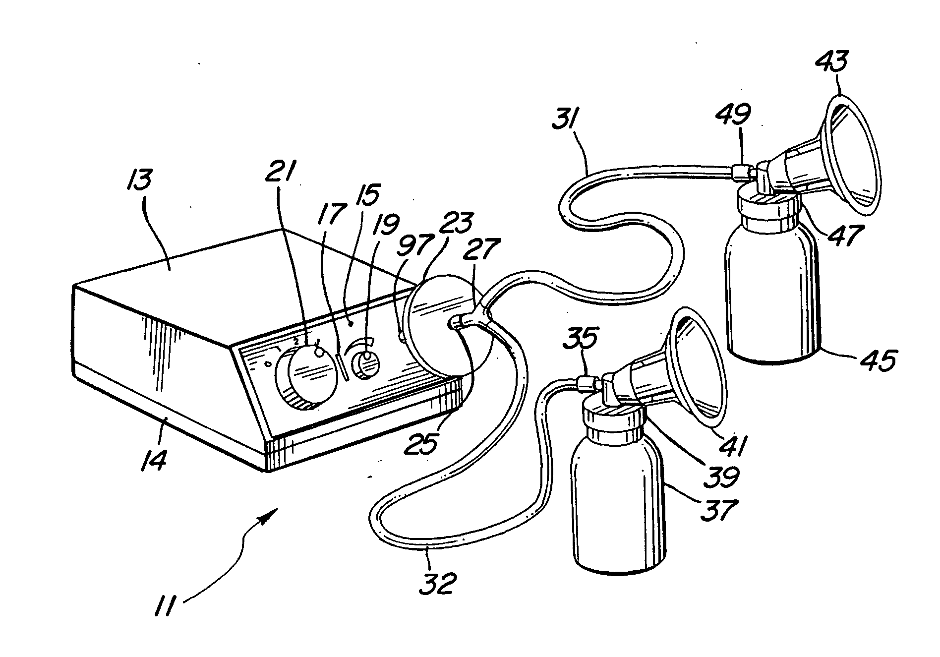
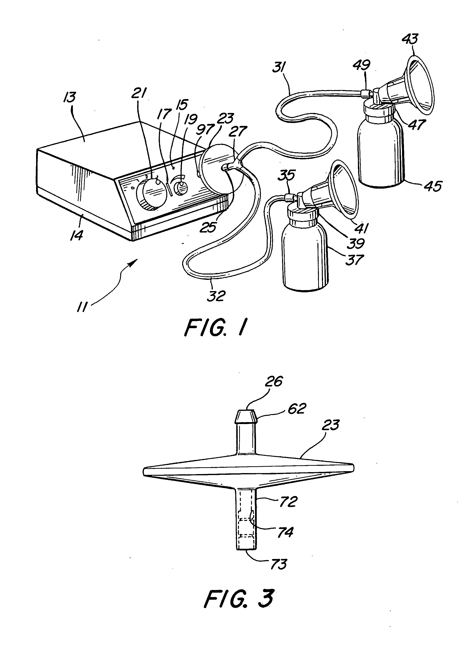
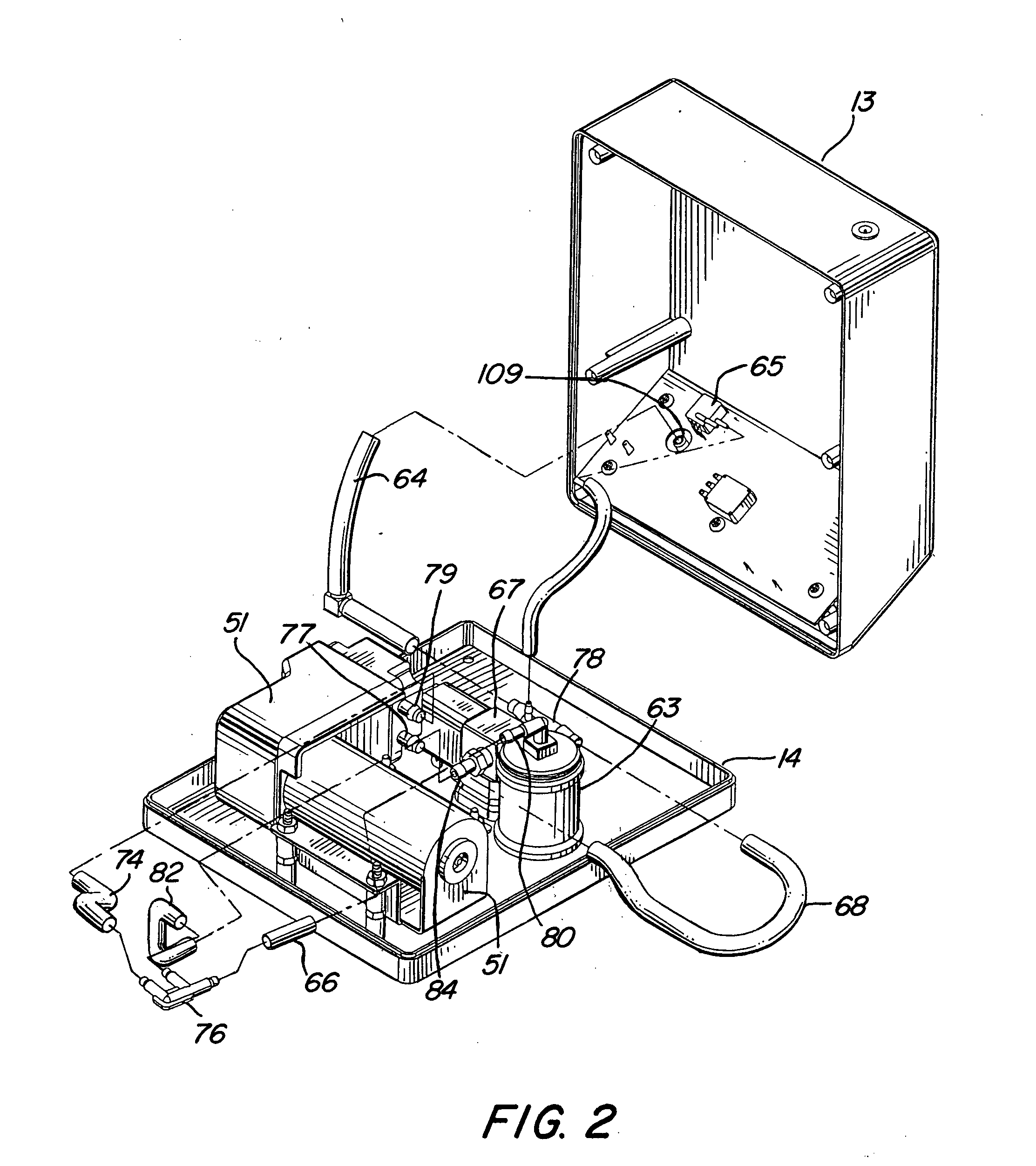
[0007] A vacuum control circuit controls the amount of time pressure is applied to the breast and the amount of time no pressure is applied to the breast within each suction cycle. The cycle rate of the pump is selected by the user and is independent of the user's selected pressure and refractory time. Both the pressure and refractory time are independent of one another. A disposable biological filter isolates the breast cup from the pump. The biological filter connects the milk collection system to the pump by an easily engageable push-on connector mechanism. The vacuum level applied to the breast cup is electronically monitored. The vacuum control circuit controls a valve in the vacuum line to keep the vacuum at a level set by the user. A second predetermined higher vacuum level set into the control circuit is used as a safety threshold. The vacuum pump is shut down by the control circuit when this higher level is sensed. The breast cup is designed to collapse in a progressively controlled way so that the areola area of the breast is squeezed first and then the teat.

Problems solved by technology

Although the prior art breast pumps and, specifically, the prior art breast pump described and claimed in U.S. Pat. No. 6,383,163 are very effective, these prior art pumps do not contemplate controlling the refractory time of the suction cycle.
The result is that the pump is not as efficient as it could be in removing the breast milk.
As a result of this decreased efficiency, a longer overall pumping period is required.
The longer period increases the physical demands on the user.
Moreover, most prior art breast pumps only apply a suction face to the breast for expressing the mother's milk.
Control of the refractory time results in a substantial increase in the amount of milk collected over a given time period.

Method used


Image

  • Electrical breast pump
  • Electrical breast pump
  • Electrical breast pump

Examples


Embodiment Construction

[0023] Reference will now be made to the preferred embodiments of the invention, examples of which are illustrated in the accompanying drawings. While the invention will be described in conjunction with the preferred embodiments, it will be understood that these embodiments are not intended to limit the invention. On the contrary, the intention is intended to cover alternatives, modifications and equivalents, which may be included within the spirit and scope of the invention as defined by the appended claims. In the following detailed description, numerous specific details are set forth in order to provide a thorough understanding of the present invention. However, it will be understood by one of ordinary skill in the art that the present invention may be practiced without these specific details. In other instances, well known methods, procedures, components, and circuits have not been described in detail so as not to unnecessarily obscure the important aspects of the present invent...


PUM


Abstract

A vacuum control system controls the amount of time that pressure is applied to a breast and the amount of time no pressure is applied to the breast, independent of the vacuum level. The amount of time that pressure is applied to a breast and the amount of vacuum applied to the breast cups can be varied by the user. A disposable biological filter isolates the pump from the breast cups. The biological filter is packaged in a housing that has an O-ring push-in connector to connect the collection system to the pump. The vacuum applied to the breast cups is monitored. The control system maintains the vacuum at a level set by the user. A second higher level is used as a safety threshold. The control system shuts down the pump when this higher level is sensed. The breast cup is constructed to provide a controlled collapse when vacuum is applied to mimic the suckling of an infant.

Description

BACKGROUND OF THE INVENTION [0001] 1. Field of the Invention [0002] The present invention relates generally to improvements in breast pumps and, more particularly, pertains to a new and improved method and apparatus for extracting milk from the breast. [0003] 2. Description of Related Art [0004] Most prior art breast pumps designed for extracting milk are concerned only with controlling the rate at which a negative pressure is applied to the breast and, in some cases, the amount of negative pressure. An example of an electric breast pump which does more than this is illustrated in the U.S. Pat. No. 6,383,163 granted May 7, 2002 to two of the three named joint inventors of the present invention. The disclosure of U.S. Pat. No. 6,383,163 is expressly incorporated herein by reference. [0005] Although the prior art breast pumps and, specifically, the prior art breast pump described and claimed in U.S. Pat. No. 6,383,163 are very effective, these prior art pumps do not contemplate contro...

Claims


Application Information

Patent Timeline
IPC IPC(8): A61M1/06
CPCA61M1/06A61M1/0031A61M1/066A61M1/74A61M1/06935
Inventor KELLY, PATRICIA A.ORTIZ, JOAN P.MCCUSKER, DAVID R.
Owner KELLY PATRICIA A
Learn More