
Device and method for kinematic calibration of robots

a robot and kinematic calibration technology, applied in the direction of electrical programme control, instruments, gearing, etc., can solve the problems of affecting the accuracy of the robot, and affecting the overall accuracy of the robot manipulator

Inactive Publication Date: 2005-02-17
GWANGJU INST OF SCI & TECH
View PDF3 Cites 42 Cited by
  • Summary
  • Abstract
  • Description
  • Claims
  • Application Information

AI Technical Summary

Benefits of technology

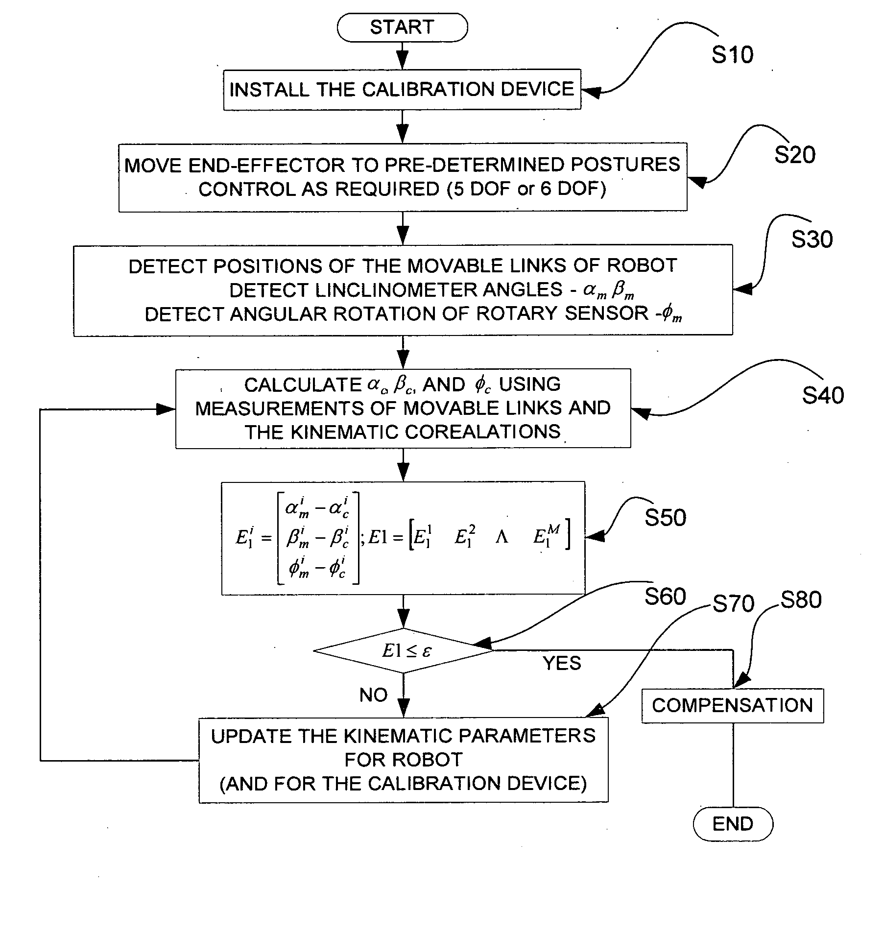
The present invention is conceived to solve the aforementioned problems. An object of the present invention is to provide a device and method for kinematic calibration of robots, wherein the robot is moved to various postures in a state where some degrees of freedom (DOF) are constrained, and the amount of compensation is determined by minimizing the errors between the values measured by the calibration device and those computed through the kinematic model.

Problems solved by technology

Due to factors like manufacturing tolerances, assembly errors etc., the actual geometric parameters differ from the nominal design parameters.
Using the mathematical model based on the nominal parameters, therefore, results in accuracy deterioration of the robot.
Errors in length of links and position of joints are the typical examples of geometric errors, whereas gear backlash and friction are the main sources of non-geometric errors.
Generally, the geometric errors have higher magnitudes and dominate the overall accuracy of the robot manipulators.
Many of the existing calibration methods using partial posture measurements lack this potential, and consequently their compensation is prone to low reliability and variation of accuracy in the workspace of the robot.

Method used


Image

  • Device and method for kinematic calibration of robots
  • Device and method for kinematic calibration of robots
  • Device and method for kinematic calibration of robots

Examples


Embodiment Construction

Hereinafter, preferred embodiments of the present invention will be described in detail with reference to the accompanying drawings.

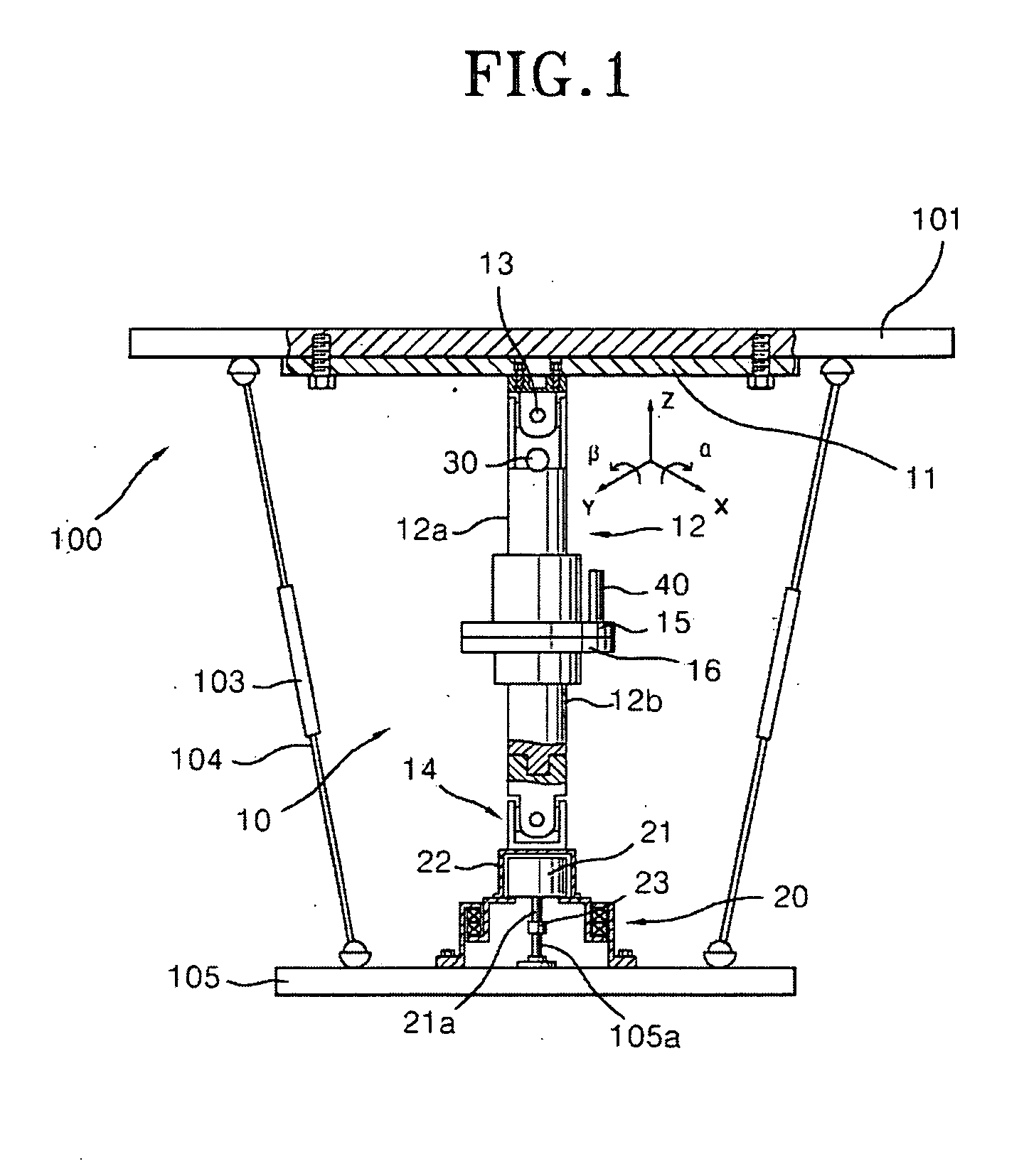
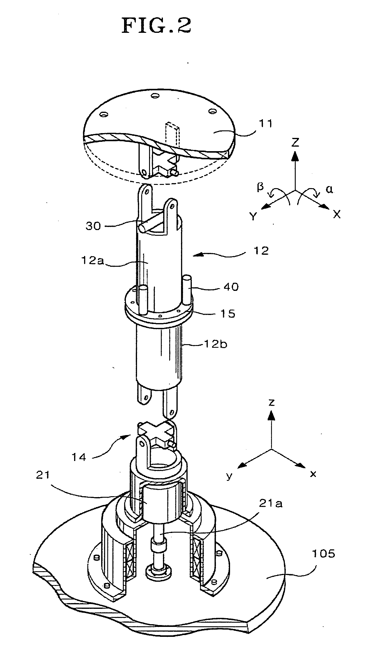
A device for kinematic calibration of a robot according to the present invention is mounted on the robot and an amount of compensation is determined by minimizing the cost function based on the difference between the measured and the computed values for position and orientation component(s) of the end-effector of the robot, where the computed values are based on the length of moveable links measured by the internal sensors and the existing values of the kinematic parameters, such that while performing measurements, the robot may be controlled in a state where some of its degrees of freedom are constrained. An embodiment of the device is shown in FIGS. 1 and 2.

Referring to these figures, the calibration device 10 has a structure capable of calibrating a robot 100 that has an end-effector 105 supported by six movable links 104 with respective actuato...


PUM


Abstract

The present invention provides a device for kinematic calibration of a robot, comprising a supporting member fixed to the base of a robot; a constraint link installed between the supporting member and an end-effector of the robot connected to the base of the robot through a plurality of movable links so as to constrain a distance between the base and the end-effector of the robot; two joints installed at the constraint link; a mean to detect angular rotation for measuring angular rotation of the end-effector when the end-effector of the robot moves to a predetermine posture; a mean to detect inclination of the constrain link installed at the constraint link about two mutually perpendicular axes for measuring inclination of the constraint link about X and Y axes; a mean to detect variation of the length for measuring variation of length of the constraint link.

Description

BACKGROUND OF THE INVENTION 1. Field of the Invention The present invention is related to a device and method for kinematic calibration of robots, and more particularly, it is related to a device and method for kinematic calibration of parallel robot manipulators. 2. Description of the Prior Art The accuracy of a robot is considered as a very important performance measure. The accuracy of robot depends on its controller and the accuracy of the geometric (kinematic) parameters that define the mathematical model of the robot in its controller. Due to factors like manufacturing tolerances, assembly errors etc., the actual geometric parameters differ from the nominal design parameters. Using the mathematical model based on the nominal parameters, therefore, results in accuracy deterioration of the robot. Errors that deteriorate the accuracy can be divided into two categories: the geometric errors and the non-geometric errors. Errors in length of links and position of joints are the...

Claims


Application Information

Patent Timeline
IPC IPC(8): B25J11/00B25J9/10B25J9/16F16H21/46G05B19/18
CPCB25J9/1692B25J9/1623
Inventor RAUF, ABDULRYU, JEHAKIM, JONG-PHILKIM, SUNG-GWON
Owner GWANGJU INST OF SCI & TECH
Learn More