Dispensing system and squeezing-out device and storage container for the dispensing system

a technology of squeezing out device and dispensing system, which is applied in the direction of liquid transfer device, transportation and packaging, flexible tubular containers, etc., can solve the problems of increasing the complexity of the construction of the known squeezing out mechanism, the inability to meet the needs of commercial use, and the replacement of empty tubes by users. cost, the effect of reducing the cost of consumable materials

Inactive Publication Date: 2005-02-10
HILTI AG
View PDF10 Cites 6 Cited by
  • Summary
  • Abstract
  • Description
  • Claims
  • Application Information

AI Technical Summary

Benefits of technology

[0015] The components of the multicomponent compound can be dispensed or squeezed out of the packaging containers by the rolling roller. A squeezing-out mechanism according to the invention does not include a connecting rod and plunger as dispensing mechanism, so that it can be constructed in a simpler, more compact manner compared to the known squeezing-out mechanisms for a plurality of components.
[0036] The storage container is advantageously enclosed by a removable protective packaging. The protective packaging is preferably adapted to the conditions for the storage of the storage container and protects the component packagings arranged on the flat supporting structure and their contents from external influences such as changing temperatures, air humidity or light. The storage container according to the invention is preferably enclosed by a removable UV-protective packaging. The protective packaging is preferably removed shortly before using the storage container. The protective packaging can be provided with a resealable closure for repeated use of the protective packaging or for repackaging a partially spent storage container.

Problems solved by technology

A disadvantage in these systems consists in a costly replacement of empty tubes with new, filled tubes by the user.
Further, due to the components being packaged in tubes, there is a large amount of packaging material to be recycled in proportion to the dispensed compound so that these systems are not suitable for commercial use, e.g., for filling a plurality of bore-holes.
The known solution is disadvantageous in that with more than two components to be dispensed, the construction of the known squeezing-out mechanisms becomes more complicated and, therefore, more costly to produce, which has disadvantageous results particularly with respect to performance capability and manufacturing costs.

Method used


Image

  • Dispensing system and squeezing-out device and storage container for the dispensing system
  • Dispensing system and squeezing-out device and storage container for the dispensing system
  • Dispensing system and squeezing-out device and storage container for the dispensing system

Examples


first embodiment

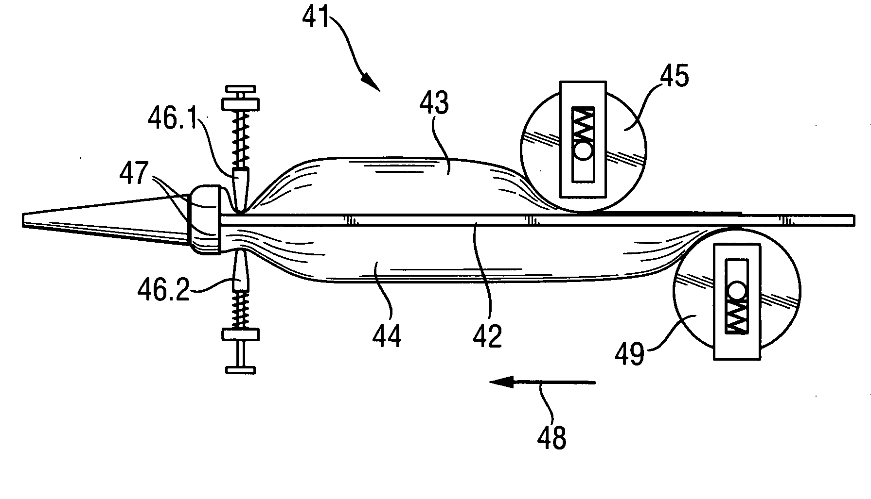
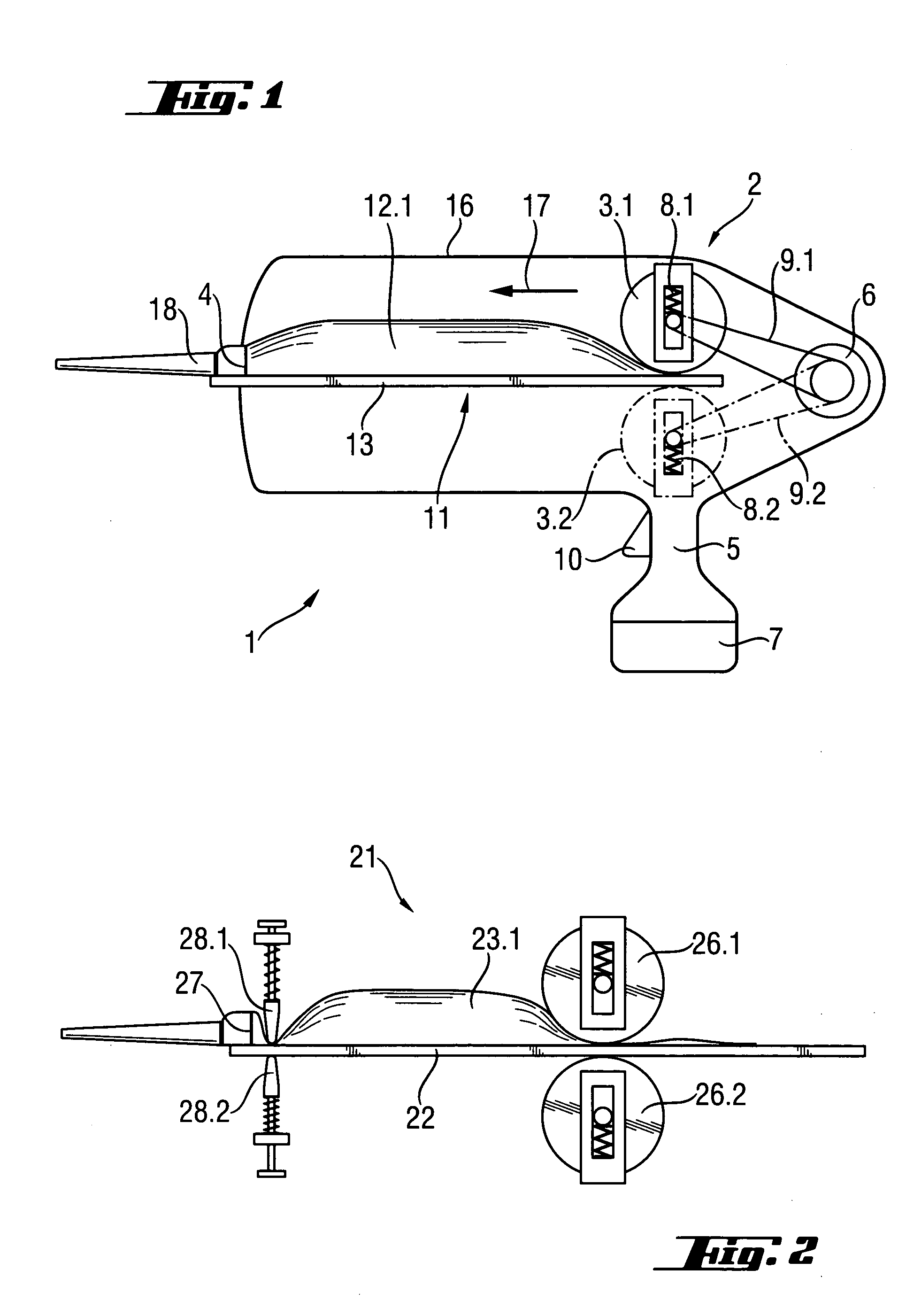
[0051] A detailed view of elements of a squeezing-out mechanism according to the invention is shown in FIG. 2. The storage container 21 has a plate 22 serving as flat supporting structure and packagings (only packaging 23.1 is shown) arranged on the latter. In FIG. 2, only individual functional parts of the entire squeezing-out device are shown, these functional parts being substantially enclosed by a housing, not shown. The squeezing-out process is carried out with the first roller 26.1 which is moved in the direction of the plate 22 by a spring force. In order that the plate 22 of the storage container 21 is not subjected to severe bending loads by the spring-biased roller 26.1 and can, accordingly, be formed with a reduced thickness which reduces the consumption of the material, a second roller 26.2 which is movable synchronously with the first roller 26.1 is provided in the embodiment. The second roller 26.2 is likewise spring-biased in a spring-elastic manner in the direction o...

second embodiment

[0059] a storage container according to the invention is shown in FIG. 6. The storage container 61 comprises a plate 62 to which are welded a first packaging 63 and a second packaging 64, each with one component of a two-component compound. The packaging 64 is shorter than packaging 63 with reference to the longitudinal axis 65. At the start of the squeezing-out process, only the component in the first packaging 63 is dispensed through the dispensing sleeve 67 along the excess length 66. As soon as the squeezing-out mechanism has reached the rear edge 68 of the second packaging 64, both packagings 63 and 64 and, therefore, both components of the two-component compound are squeezed out as the squeezing-out process continues.

third embodiment

[0060] a storage container according to the invention is shown in FIG. 7. The storage container 71 has two packagings 73 and 74 arranged at its plate 72 which have a varying volume cross-section along the longitudinal axis 75 of the plate 72. By means of this arrangement of the packagings 73 and 74, the characteristics of the multicomponent compound to be produced can be controlled over the course of the squeezing-out process corresponding to the characteristics and the supplied amount of the individual components in packagings 73 and 74.

[0061]FIG. 8 shows a detailed cross-section of two variants for fastening the component packagings to the combining chamber. E.g., two connection pieces 82 and 93 for the connection of packaging 83 and packaging 93 are formed at the combining chamber 81. One fastening variant is represented by the connection of packaging 83 to the connection piece 82, and another fastening variant is shown by the connection of packaging 92 to the connection piece 92...


PUM


Abstract

A system for dispensing at least two components of a multicomponent mass, includes a squeezing-out device (2) having a dispensing opening (4) and at least one rolling roller (3.1, 3.2) for dispensing the at least two components; a storage container (11) having flat support element (13) on which packagings of the at least two components are supported; and a spring (8.1, 8.2) for biasing the at least one rolling roller (3.1, 3.2) in a direction toward the flat support element (13) substantially perpendicular thereto.

Description

BACKGROUND OF THE INVENTION [0001] 1. Field of the Invention [0002] The invention relates to a system for dispensing at least two components of a multicomponent compound and which comprises a squeezing-out mechanism and a storage container. The squeezing-out mechanism has a dispensing opening and at least one rollable roller for dispensing the components. At least two components of the multicomponent compounds, which can be dispensed by the squeezing-out mechanism, are arranged on the storage container. Further, the invention is directed to a squeezing-out mechanism, particularly for a system of the type mentioned above, and a storage container for at least two components of a multicomponent compound, particularly for a system of the type described above. [0003] 2. Description of the Prior Art [0004] U.S. Pat. No. 3,302,832 A, e.g., discloses mechanism for squeezing-out a two-component compound whose individual components are packaged in tubes, wherein the tubes are pressed simultan...

Claims


Application Information

Patent Timeline
IPC IPC(8): B05C17/005
CPCB05C17/005B05C17/00583B05C17/00553
Inventor WOERSDOERFER, UDOKOEGLER, MARKUS
Owner HILTI AG
Why Eureka
Try Eureka