
Current reduction by dynamic receiver adjustment in a communication device

a communication device and dynamic adjustment technology, applied in the direction of transmission monitoring, modulation, electrical apparatus, etc., can solve the problems of high current drain of receivers, non-linear distortion of cross-modulation and intermodulation, and inability to make the most efficient use of current drain in the prior ar

Active Publication Date: 2005-02-03
GOOGLE TECH HLDG LLC
View PDF7 Cites 52 Cited by
  • Summary
  • Abstract
  • Description
  • Claims
  • Application Information

AI Technical Summary

Problems solved by technology

This situation leads to narrow band interference signals that cause both crossmodulation and intermodulation non-linear distortions.
These two factors cause receivers to operate with higher current drain than needed under the majority of usage conditions.
Interference is a particular problem in CDMA systems which require the receiver and transmitter to be on continuously.
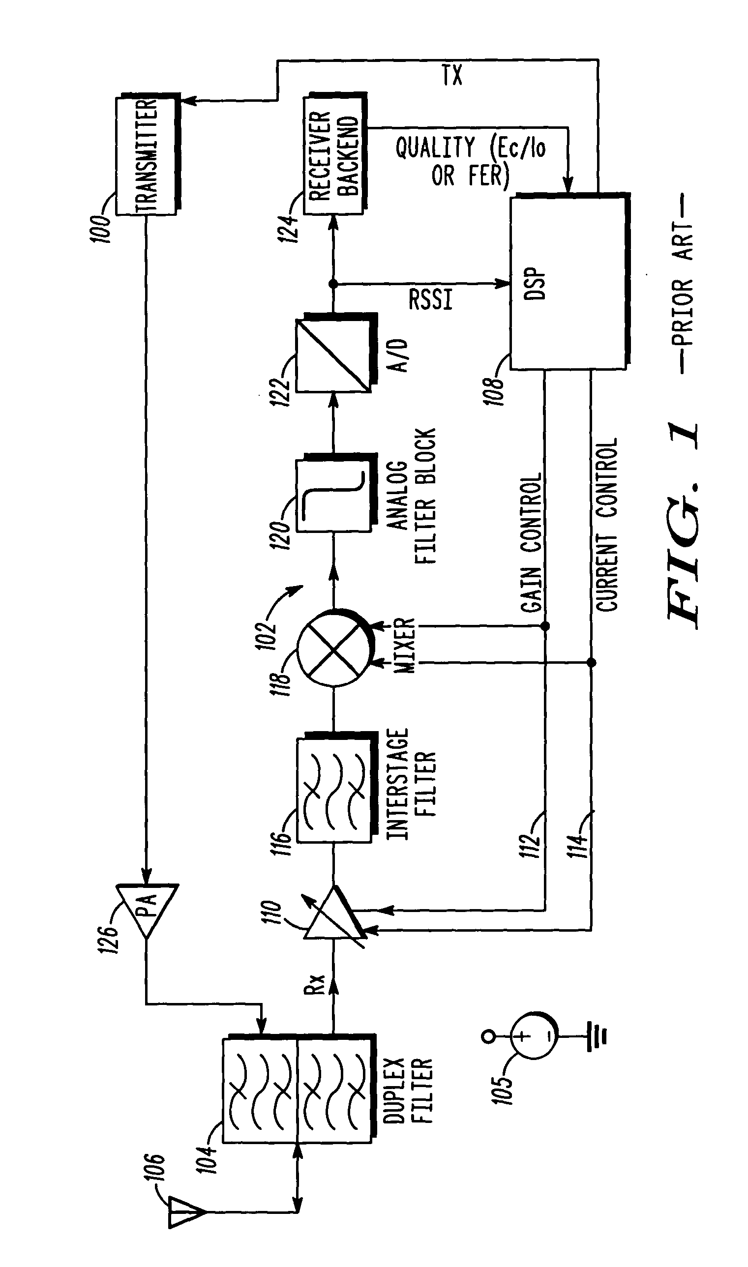
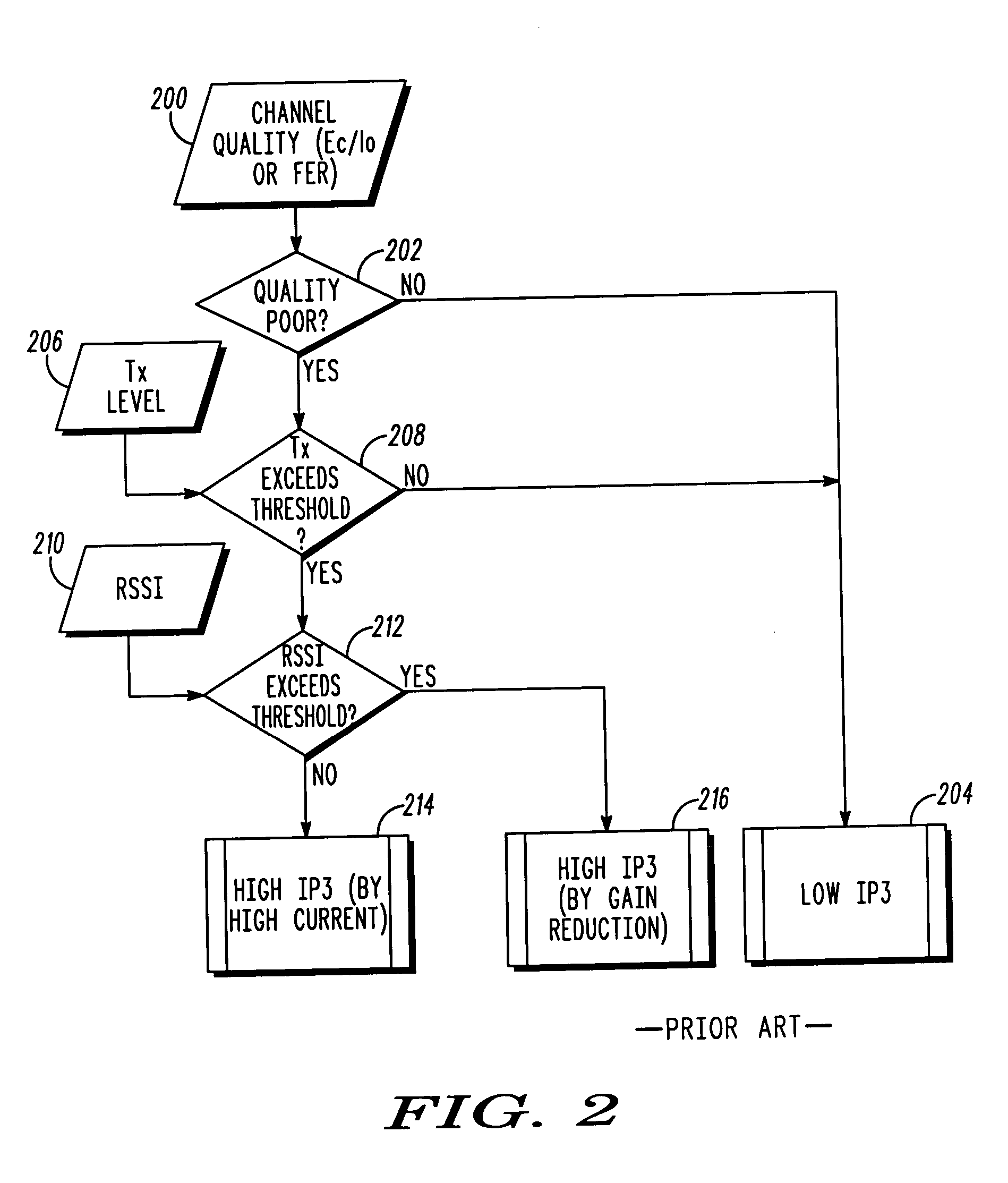
However, the prior art does not make the most efficient use of current drain since the linearity is potentially increased without any knowledge of the interference.
Poor quality can be caused by a number of factors that are not related to receiver linearity and thus is not the most efficient metric.
Furthermore, the prior art does not address the use of variable dynamic range in the baseband.
Also, the mitigation is limited to LNA bypass and thus limits the optimization of performance near sensitivity.
Furthermore, detection of the intermodulation products is much more difficult than detection of the interference since the intermodulation products are several dB lower in amplitude than the actual interference.
This limits the efficacy of the techniques to mitigation of narrow-band interferer by the A / D and does not provide a mechanism to reduce the current drain of the other circuit elements, e.g. digital filters, analog filters, and RF circuits.

Method used


Image

  • Current reduction by dynamic receiver adjustment in a communication device
  • Current reduction by dynamic receiver adjustment in a communication device
  • Current reduction by dynamic receiver adjustment in a communication device

Examples


Embodiment Construction

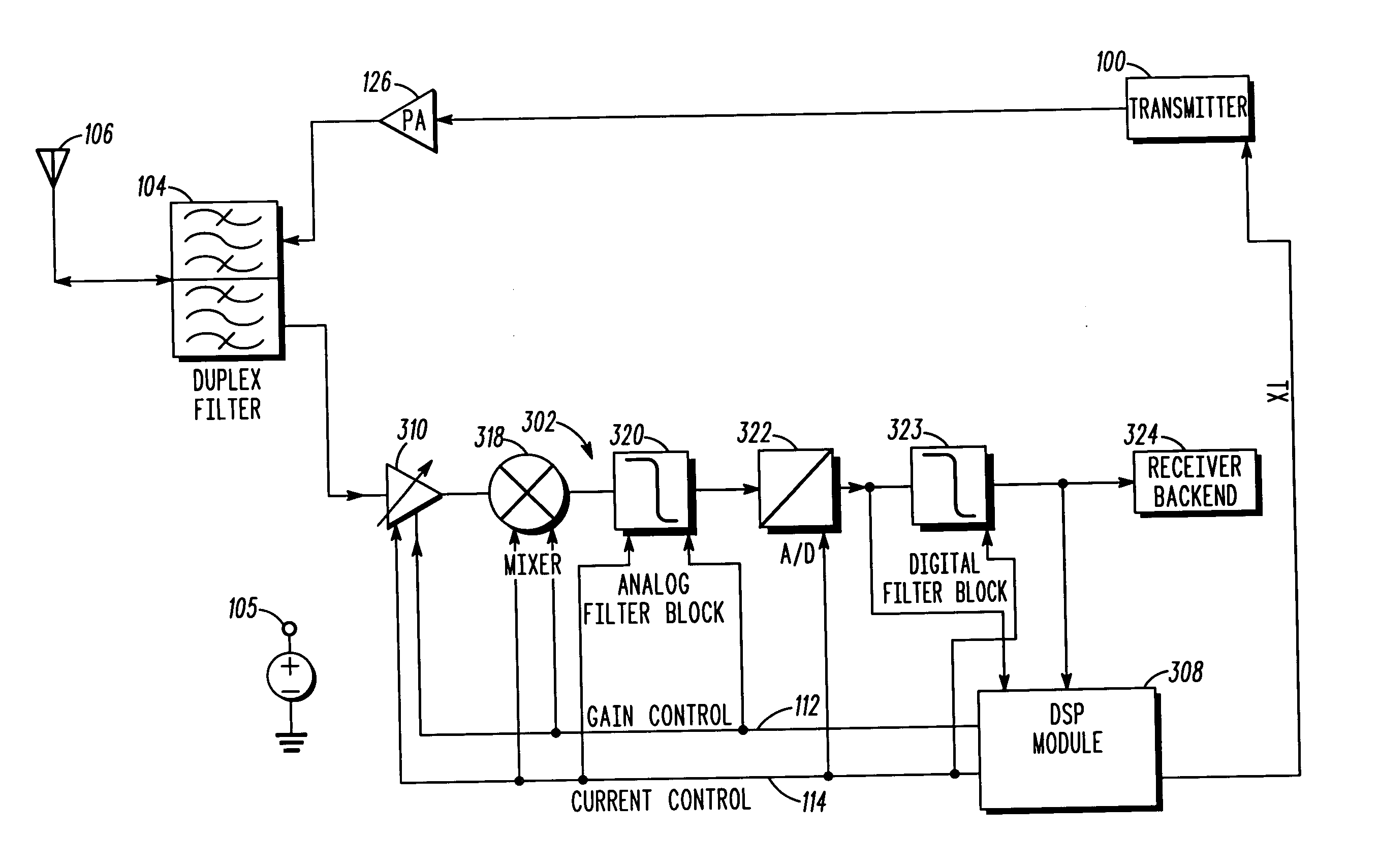
The present invention provides a unique method to improve reception in a receiver circuit for a wireless communications device in a communication system while reducing current drain. This is done by reducing the current drain in the receiver by making the elements in the receiver (mixers, amplifiers and filters) less linear when there is little or no interference, and increasing linearity again when interference exists. In particular, the present invention reduces the effects of intermodulation distortion and crossmodulation distortion by direct determination of the interference, instead of relying on channel quality, and by improving linearity of the receiver only when non-linear distortion products are anticipated. This improvement is accomplished without any significant additional hardware or cost in the communication device. Moreover, the present invention can take advantage of existing high dynamic range devices such as analog-to-digital converters and digital filters in combi...


PUM


Abstract

A method for reducing current drain in a communication device includes a first step of detecting interference including intermodulation and crossmodulation products. A next step includes determining a frequency offset of the interference with reference to the operating receiver band. A next step includes measuring a power level of the interference. A next step includes calculating a receiver linearity required to achieve a desired signal-to-interference ratio. A next step includes adjusting the receiver linearity in order to achieve the desired signal-to-interference ratio. Optionally, the receiver dynamic range can be adjusted to suit the reduced signal swing due to the reduced linearity.

Description

FIELD OF THE INVENTION The present invention generally relates to reducing power consumption in a communication device such as a radiotelephone. More particularly, the present invention relates to a technique for dynamic adjustment of receiver elements in radiotelephone device. BACKGROUND OF THE INVENTION Code Division Multiple Access (CDMA) and Wideband CDMA (WCDMA) receivers in North American bands have been and will continue to coexist with other narrow band systems such as AMPS, IS136, and Global System for Mobile (GSM) communication system. This situation leads to narrow band interference signals that cause both crossmodulation and intermodulation non-linear distortions. The traditional method to mitigate the distortion is to operate with sufficiently high linearity at the expense of additional current drain. Additionally, receiver designs are migrating to higher dynamic range analog-to-digital converters (A / Ds) with digital filters and less analog filtering. This type of rec...

Claims


Application Information

Patent Timeline
IPC IPC(8): H04B1/10H04B1/707
CPCH04B1/109H04B2201/70707H04B1/71H04B1/06H04B17/00
Inventor HAUB, DAVID R.HUGHES, JAMES DAVID
Owner GOOGLE TECH HLDG LLC
Learn More