
Intramedullary nail system and method for fixation of a fractured bone

a technology of intramedullary nail and fractured bone, which is applied in the field of intramedullary nail system and method for fixing fractured bone, can solve the problems of difficult for surgeons to locate such nails, and achieve the effect of preventing rotational and longitudinal movemen

Inactive Publication Date: 2005-01-13
GOTFRIED YECHIEL
View PDF11 Cites 85 Cited by
  • Summary
  • Abstract
  • Description
  • Claims
  • Application Information

AI Technical Summary

Benefits of technology

In some embodiments of the present invention, an IM system comprises an IM nail having a head and a stem. The head of the IM nail comprises a distal portion, which typically includes at least one head hole, and a proximal portion, having a diameter less than a diameter of the distal portion. For some applications, the diameter of the proximal portion is less than about 50% of the diameter of the distal portion. Such a narrower proximal portion typically allows greater regrowth and healing of the neck of the femur towards the area of the greater trochanter, than generally occurs upon implantation of conventional IM nail heads. At the same time, because a proximal end of the narrower proximal portion generally remains easily locatable on the external surface of the femur in the area of the tip of the greater trochanter or the piriformis, a surgeon typically can readily locate the IM nail if post-operative access to the implant becomes necessary. For some applications, the IM system further comprises the sleeve locking mechanism described hereinabove.
There is additionally provided, in accordance with an embodiment of the present invention, apparatus for use with an intramedullary (IM) nail implanted in a bone of subject, the IM nail having a proximal portion and a distal portion that defines one or more holes therethrough, the apparatus including: a support, includes means for coupling the support to the proximal portion; a pin, adapted to be inserted through, at any given time, one of the holes and into the bone in a vicinity of a fracture of the bone; and means for moving the pin translationally and rotationally, so as to reduce and align the fracture, respectively.

Problems solved by technology

Without the use of this IM locating tool, it is sometimes difficult for a surgeon to locate such an IM nail if post-operative access to the implant becomes necessary.

Method used


Image

  • Intramedullary nail system and method for fixation of a fractured bone
  • Intramedullary nail system and method for fixation of a fractured bone
  • Intramedullary nail system and method for fixation of a fractured bone

Examples


Embodiment Construction

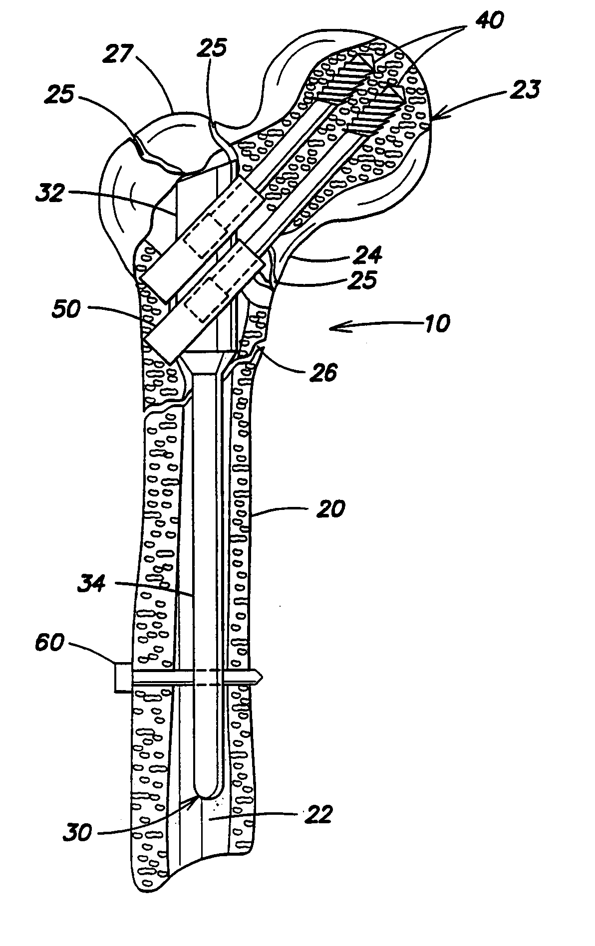
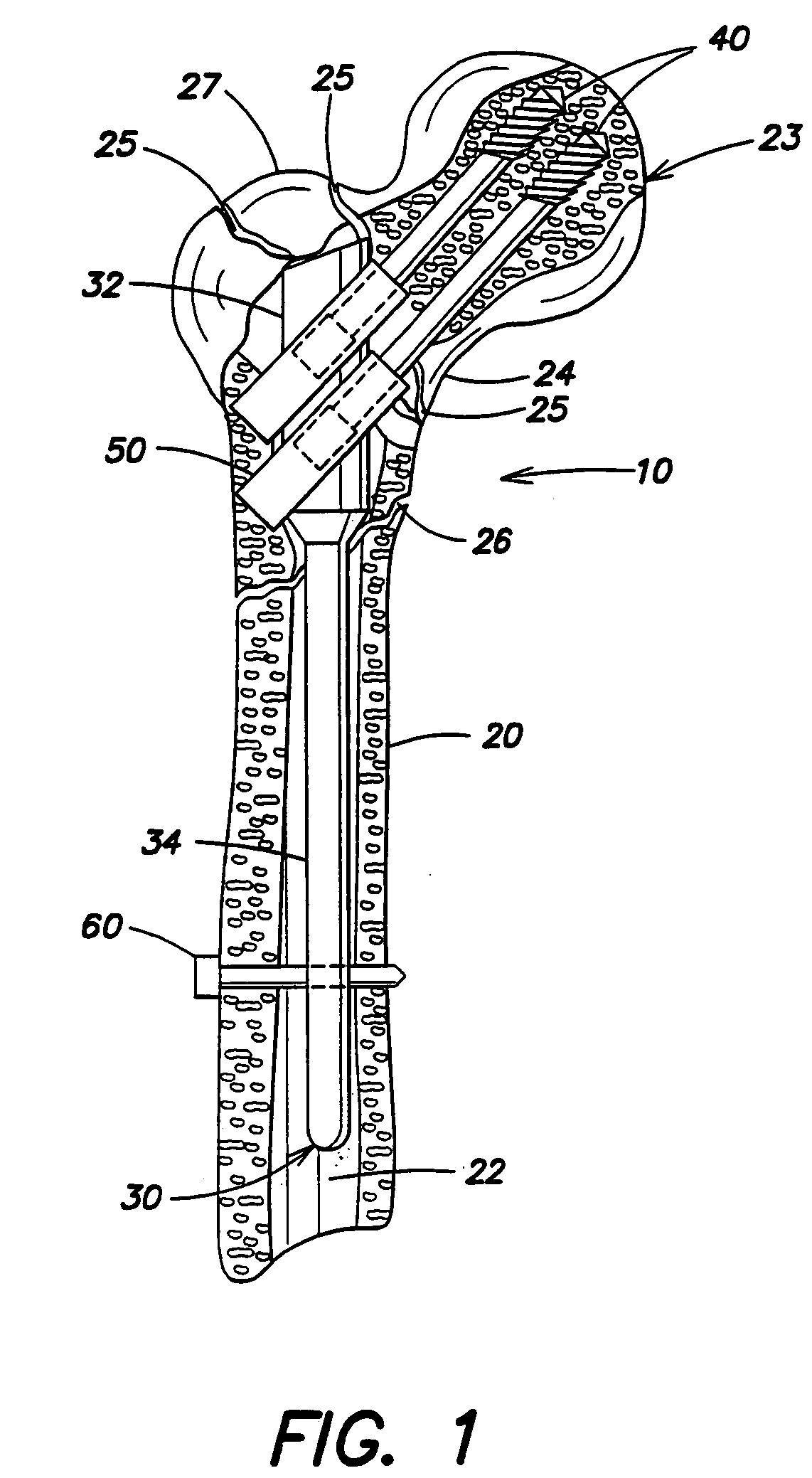
FIG. 1 is a schematic illustration of an intramedullary (IM) system 10 in place in a femur 20, in accordance with an embodiment of the present invention. The IM system comprises an IM nail 30, having a proximal head 32 and a stem 34; at least one screw 40 for securing the IM nail at the head within a femoral head 23 of femur 20; and at least one sleeve 50. Alternatively, another anchoring element, such as a nail or bolt is used, instead of screw 40. IM system 10 typically further comprises at least one distal anchoring element 60, such as a screw, nail, or bolt, to secure IM nail 30 at stem 34 within a canal 22 of femur 20. For some applications, head 32 and / or stem 34 define a longitudinal bore (not shown).

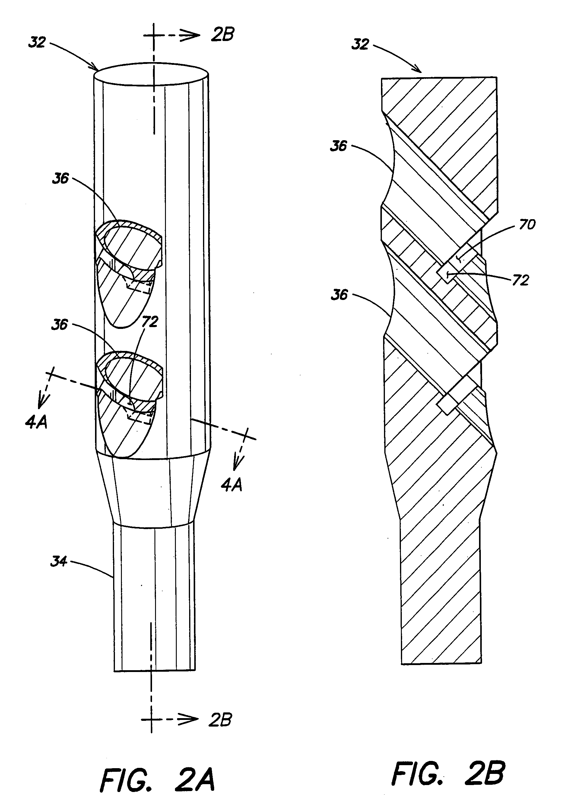
FIG. 2A is a schematic illustration of head 32 of IM nail 30, and FIG. 2B is a cross-sectional illustration of head 32 through the line A--A of FIG. 2A, in accordance with an embodiment of the present invention. Head 32 defines at least one hole 36, typically two holes, as shown ...


PUM


Abstract

Apparatus for treating a fracture of a bone of a subject includes an intramedullary (IM) nail, adapted to be inserted in a medullary canal of the bone of the subject, and having a proximal head that defines at least one hole therethrough. The apparatus also includes a sleeve, which includes a locking mechanism, which locking mechanism is adapted to engage the hole when the sleeve is inserted in the hole, such engagement preventing rotational and longitudinal movement between the sleeve and the hole. In an embodiment, the apparatus includes a screw, the sleeve being adapted to slidably receive the screw.

Description

FIELD OF THE INVENTION The present invention relates generally to implantable devices for treating femoral fractures, and specifically to an intramedullary system for coupling bone portions across a fracture. BACKGROUND OF THE INVENTION Intramedullary (IM) nails are implantable devices used to stabilize fractures and allow for bone healing. IM nails are inserted into the medullary canal of the long bones of the extremities, e.g., the femur or tibia. Currently-used IM nails have a head region that generally includes at least one hole, transverse to the longitudinal axis of the nail, for receiving anchoring means, such as a screw, to secure the nail within the medullary canal, of the bone. Some such anchoring means include at least one sleeve, which passes through the transverse hole, and through which a screw assembly typically passes freely. A proximal end of the head region protrudes from the proximal end of the bone, to facilitate post-implantation access to the IM nail, if desi...

Claims


Application Information

Patent Timeline
Patent Type & Authority Applications(United States)
IPC IPC(8): A61B17/17A61B17/58A61B17/72A61B17/78
CPCA61B17/1717A61B17/72A61B17/744A61B17/7283A61B17/7241
Inventor GOTFRIED, YECHIEL
Owner GOTFRIED YECHIEL
Learn More