Eureka AIR delivers breakthrough ideas for toughest innovation challenges, trusted by R&D personnel around the world.

Rail road car truck

a technology for rail roads and trucks, applied in the field of three-piece rail road car trucks, can solve the problems of affecting the lateral stiffness of the suspension, not necessarily providing optimal performance in dealing with other phenomena, and mediocre ride quality,

Inactive Publication Date: 2005-01-13
NATIONAL STEEL CAR
View PDF99 Cites 32 Cited by
  • Summary
  • Abstract
  • Description
  • Claims
  • Application Information

AI Technical Summary

Benefits of technology

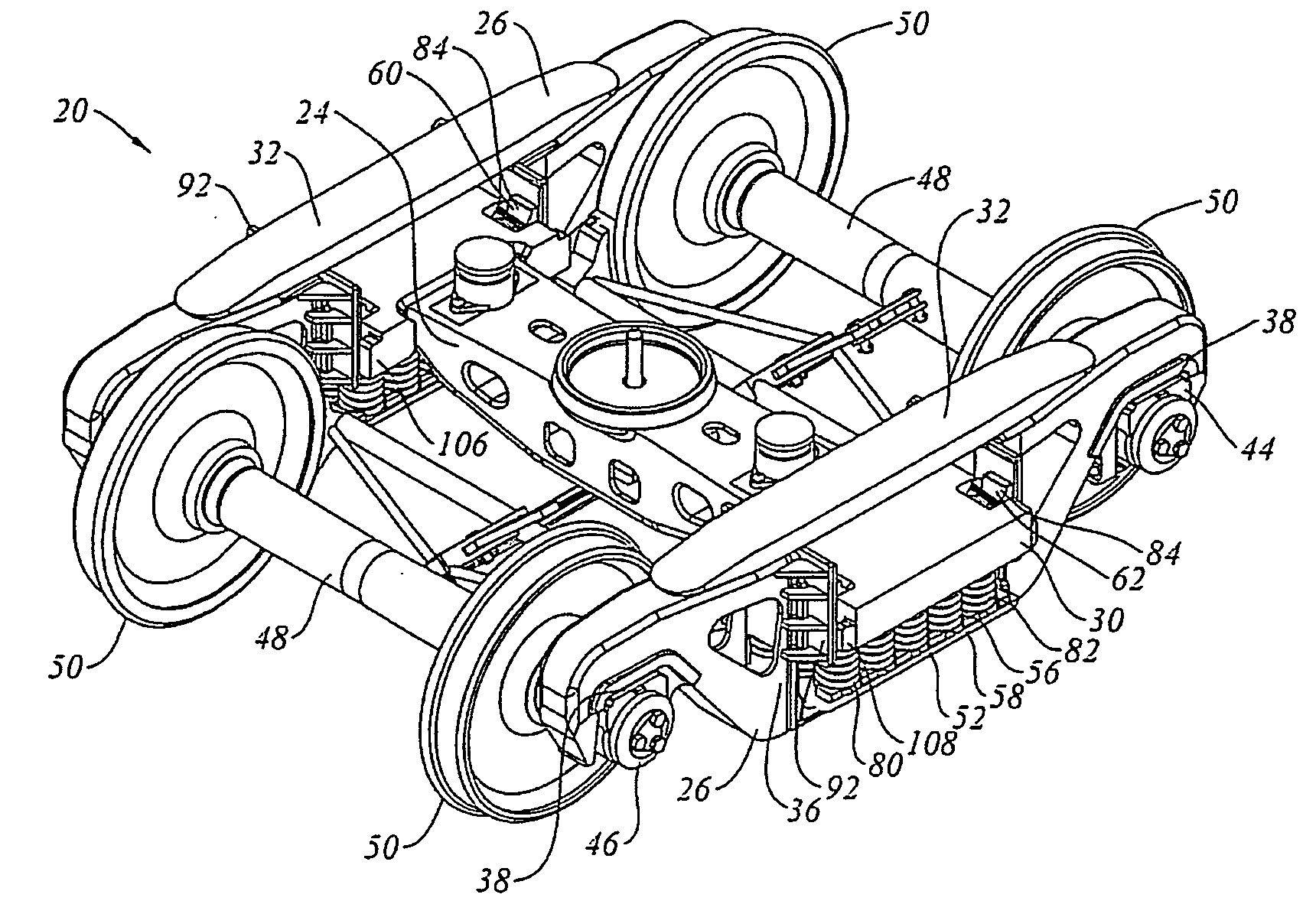
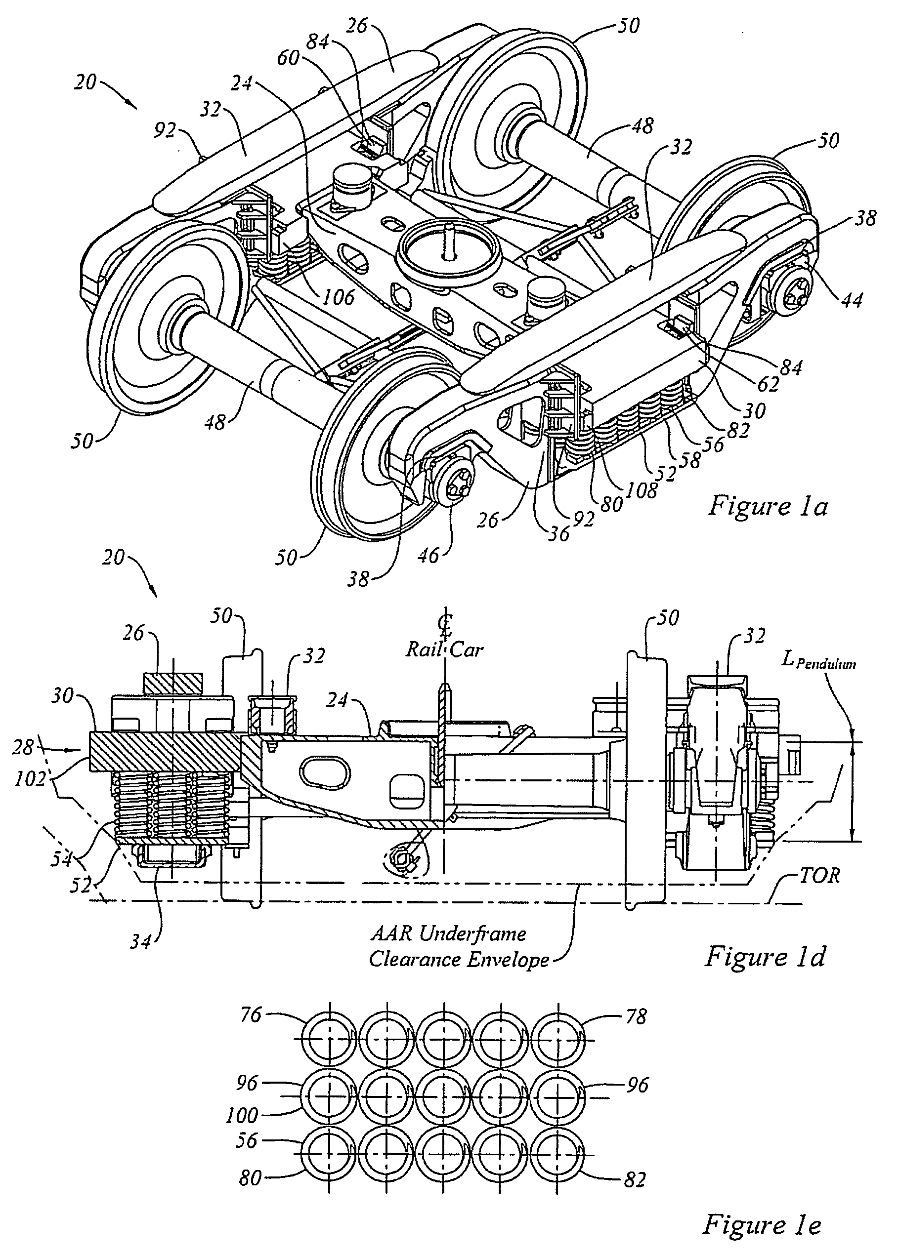
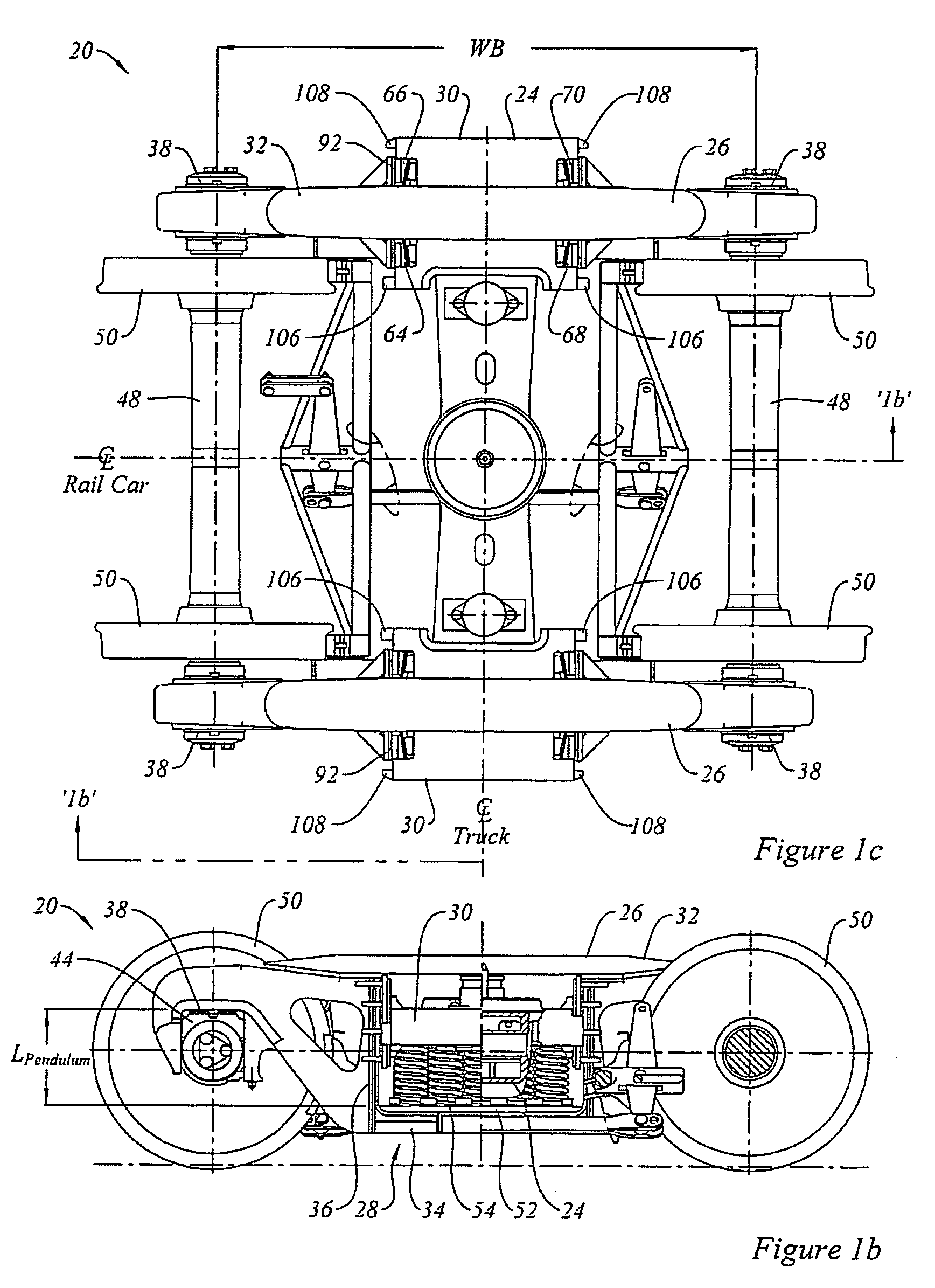
In another aspect of the invention there is a railroad car truck having a sideframe, an axle bearing, and a bi-directional rocker mounted between the sideframe and the axle bearing. In still another aspect of the invention, there is a railroad car truck having a truck bolster mounted transversely between a pair of sideframes, and wheelsets mounted to the sideframes to permit rolling operation of the truck along a set of rail road tracks. The truck includes rocker elements mounted between the sideframes and the wheelsets. The rocker elements are operable to permit lateral swinging of the sideframes and to permit self-steering of the truck.

Problems solved by technology

The 1980 Car &Locomotive Cyclopedia states at page 669 that the three piece truck offers “interchangeability, structural reliability and low first cost but does so at the price of mediocre ride quality and high cost in terms of car and track maintenance.”
There is longitudinal ride quality, where, often, the limiting condition is the maximum expected longitudinal acceleration experienced during humping or flat switching, or slack run-in and run-out.
These phenomena tend to be interrelated, and the optimization of a suspension to deal with one phenomenon may yield a system that may not necessarily provide optimal performance in dealing with other phenomena.
Thus the choice of vertical spring stiffness may strongly affect the lateral stiffness of the suspension.
That is to say, when a conventional truck enters a curve, the leading outer wheel may tend to want to pull ahead relative to the leading inner wheel, and the inner wheel may then tend to want to slip, or skid, somewhat.

Method used


Image

  • Rail road car truck
  • Rail road car truck
  • Rail road car truck

Examples


Embodiment Construction

The description that follows, and the embodiments described therein, are provided by way of illustration of an example, or examples, of particular embodiments of the principles of the present invention. These examples are provided for the purposes of explanation, and not of limitation, of those principles and of the invention. In the description, like parts are marked throughout the specification and the drawings with the same respective reference numerals. The drawings are not necessarily to scale and in some instances proportions may have been exaggerated in order more clearly to depict certain features of the invention.

In terms of general orientation and directional nomenclature, for each of the rail road car trucks described herein, the longitudinal direction is defined as being coincident with the rolling direction of the rail road car, or rail road car unit, when located on tangent (that is, straight) track. In the case of a rail road car having a center sill, the longitudi...


PUM


Abstract

A rail road freight car truck has a truck bolster and a pair of side frames, the truck bolster being mounted transversely relative to the side frames. The mounting interface between the ends of the axles and the sideframe pedestals allows lateral rocking motion of the sideframes in the manner of a swing motion truck. The lateral swinging motion is combined with a longitudinal self steering capability. The self steering capability may be obtained by use of a longitudinally oriented rocker that may tend to permit resistance to self steering that is proportional to the weight carried across the interface. The trucks may have auxiliary centering elements mounted in the pedestal seats, and those auxiliary centering elements may be made of resilient elastomeric material. The truck may also have friction dampers that have a disinclination to stick-slip behaviour. The friction dampers may be provided with brake linings, or similar features, on the face engaging the sideframe columns, on the slope face, or both.

Description

FIELD OF THE INVENTION This invention relates to the field of rail road cars, and, more particularly, to the field of three piece rail road car trucks for rail road cars. BACKGROUND OF THE INVENTION Rail road cars in North America commonly employ double axle swivelling trucks known as “three piece trucks” to permit them to roll along a set of rails. The three piece terminology refers to a truck bolster and pair of first and second sideframes. In a three piece truck, the truck bolster extends cross-wise relative to the sideframes, with the ends of the truck bolster protruding through the sideframe windows. Forces are transmitted between the truck bolster and the sideframes by spring groups mounted in spring seats in the sideframes. The sideframes carry forces to the sideframe pedestals. The pedestals seat on bearing adapters, whence forces are carried in turn into the bearings, the axle, the wheels, and finally into the tracks. The three piece truck relies upon a suspension in the ...

Claims


Application Information

Patent Timeline
Patent Type & Authority Applications(United States)
IPC IPC(8): B61F5/06B61F5/12B61F5/30B61F5/38
CPCB61F5/06B61F5/38B61F5/305B61F5/12
Inventor FORBES, JAMES W.HEMATIAN, JAMAL
Owner NATIONAL STEEL CAR
Why Eureka
Eureka Blog
Learn More