
Design and control method of a micro-nanometer precision servo pneumatic X-Y positioning table

a technology of precision servo and positioning table, which is applied in the direction of electric programme control, program control, instruments, etc., to achieve the effect of high positioning precision

Inactive Publication Date: 2005-01-06
SHIH MING CHANG +1
View PDF9 Cites 19 Cited by
  • Summary
  • Abstract
  • Description
  • Claims
  • Application Information

AI Technical Summary

Benefits of technology

[0006] A micro-nanometer precision servo pneumatic X-Y positioning table comprises by two slide air cylinders and drive the two slide air cylinders by servo control rule to make the pneumatic table to get the purpose of X-Y two degrees of freed precision positioning. However, the pneumatic servo system is a high time-variant and nonlinear system and the nonlinear friction force causes the stick-slip phenomenon of the pneumatic servo system. Therefore the micro-nanometer precision servo pneumatic X-Y positioning table in accordance with the present invention has a new velocity feedback compensation method to overcame the nonliner friction force and ...

Problems solved by technology

However, the pneumatic servo system is a high time-variant and nonlinear system and the nonlinear friction force causes the stick-slip phenomenon of the pneumatic servo system.

Method used


Image

  • Design and control method of a micro-nanometer precision servo pneumatic X-Y positioning table
  • Design and control method of a micro-nanometer precision servo pneumatic X-Y positioning table
  • Design and control method of a micro-nanometer precision servo pneumatic X-Y positioning table

Examples


Embodiment Construction

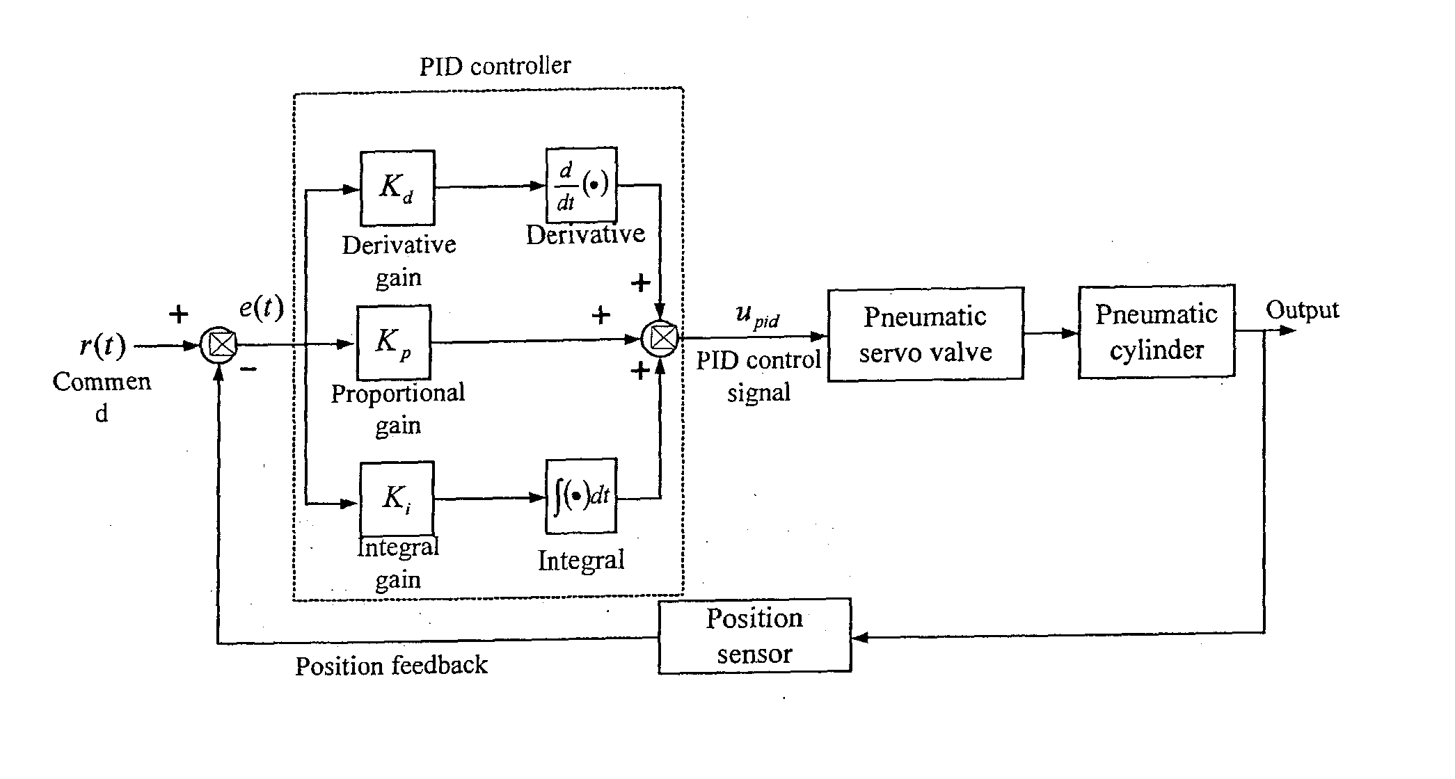
[0016]FIG. 2 is a block diagram of the hardware of a micro-nanometer precision servo pneumatic X-Y positioning table and the control compensation method in accordance with the present invention. The micro-nanometer precision servo pneumatic X-Y positioning table comprises by two slide air cylinders 21&31. The present invention is a pneumatic positioning table, which is able to move toward both X-axis and Y-axis. The slide air cylinder on the X-axis 21 has a positioning sensor optical scale 23 which resolution is micro-nanometer class (e.g. 1 um, 1 nm, 20 nm resolution) to measure the displacement of the positioning table on the X-axis 22. Put the slide air cylinder on the Y-axis 31 on the positioning table on the X-axis 22. The slide air cylinder on the Y-axis 31 has a positioning sensor, optical scale 33, which measure the displacement of the positioning table on the Y-axis 32. Therefore, the X-Y table is established, and then the positioning table on the Y-axis 32 is able to move ...


PUM


Abstract

A micro-nanometer precision servo pneumatic X-Y positioning table comprises by two slide air cylinders and drives the two slide air cylinders by the servo control rule to make the pneumatic table to get the purpose of X-Y two degrees of freedom precision positioning. However, the pneumatic servo system is a high time-variant and nonlinear system and the nonlinear friction force; causes the stick-slip phenomenon of the servo pneumatic system. Therefore the. micro-nanometer precision servo pneumatic X-Y positioning table in accordance with the present invention has a new velocity feedback compensation method to overcome the nonlinear friction force and the stick-slip phenomenon. The new method is to add a velocity compensation signal, which periodic frequency is larger than the system's natural frequency into the control signals. The method is to put the velocity compensation signal directly into the servo valve control signals. By this method; it is able to avoid the complex control rules and the calculation of the feedback compensation and to get higher precision positioning. The positioning precision of the micro-nanometer servo pneumatic X-Y positioning table is about the resolution of the linear scale (ex. in this case 20 nanometer, is the resolution of the used optical linear scale; if the resolution is 10 nanometer the precision can be also 10 nanometer) not only for long stroke but also for micro-step command.

Description

BACKGROUND OF THE INVENTION [0001] 1. Field of the Invention [0002] The present invention relates to a micro-nanometer precision servo pneumatic X-Y positioning table, and more particularly to a design of a micro-nanometer precision servo pneumatic X-Y two axes positioning table and a velocity compensation control method of overcoming the nonlinear friction force of the pneumatic cylinder and of eliminating the stick-slip phenomenon of the pneumatic servo system. [0003] 2. Description of the Related Art [0004] A conventional pneumatic positioning table usually used the positioning pin, the photoelectric switch, or the magnetic switch to detect the position and lock the pneumatic cylinder. Those positioning methods are so hard to response the time difference accurately because of the time-variant and nonlinear character of the cylinder that it's hard to get high precision positioning. Recently the pneumatic servo valve is generally used to control the pneumatic servo system because o...

Claims


Application Information

Patent Timeline
IPC IPC(8): G05B19/18G05D3/14
CPCG05D3/14
Inventor SHIH, MING-CHANGPAI, KEI-PEN
Owner SHIH MING CHANG
Learn More