Eureka AIR delivers breakthrough ideas for toughest innovation challenges, trusted by R&D personnel around the world.

Using line struture information to enhance line drawing in digital systems

a line struture and digital system technology, applied in the direction of anti-aliasing details, instruments, computing, etc., can solve the problems of inaccurate line drawing, high cost, and subject to rounding errors

Inactive Publication Date: 2005-01-06
FRAUNHOFER CENT FOR RES & COMP GRAPHICS
View PDF7 Cites 3 Cited by
  • Summary
  • Abstract
  • Description
  • Claims
  • Application Information

AI Technical Summary

Problems solved by technology

A difficulty with any pixel-by-pixel approach is that it requires a determination where the next pixel will be placed relative to the last pixel for each new pixel.
As such, it is both expensive to perform and subject to rounding errors.
Moreover, because the determination must be performed with every pixel, the rounding errors may accumulate quickly and cause the line to be drawn inaccurately.

Method used


Image

  • Using line struture information to enhance line drawing in digital systems
  • Using line struture information to enhance line drawing in digital systems
  • Using line struture information to enhance line drawing in digital systems

Examples


Embodiment Construction

The following Detailed Description includes the complete Detailed Description of the parent of the present patent application; the disclosure which is new in this application begins at the section titled Additional line drawing techniques that use the line structure information.

Overview of Line Drawing with the Invention: FIG. 1

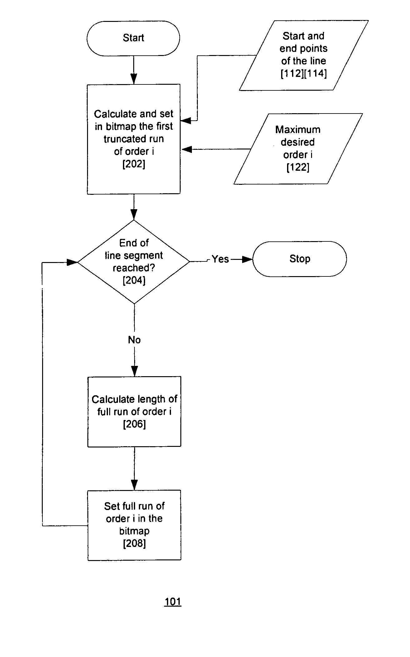
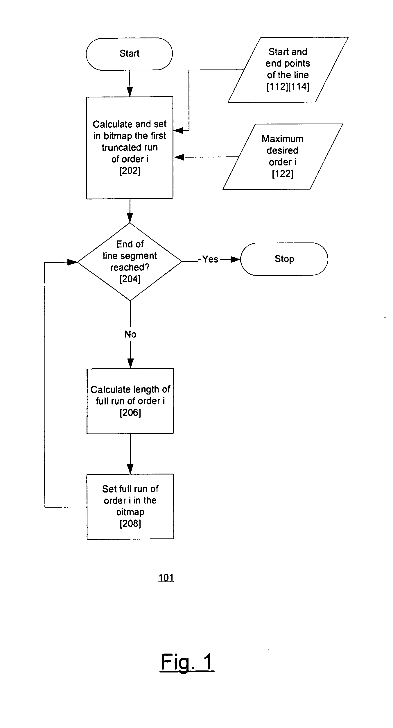
FIG. 1 is a flowchart [101] that provides an overview of how a line segment may be drawn using this invention. Starting parameters include the maximum order of the runs to be used in drawing the lines [122] and the start and endpoints of the line [112,114]. The maximum order can be predefined by the manufacturer of an apparatus based on the invention, calculated based on the characteristics of the system or based on the length of the line. In the preferred embodiment the maximum order of the runs [120] is set to two.

The line segment defined between the starting point [112] (x0, y0) and the end point [114] (x1, y1) consists of, at most, three sets of runs...


PUM


Abstract

Line drawing techniques that employ runs or runs of runs of pixels to draw the line compute line structure information that they use to determine the sequence of runs in the line. This line structure information may be used in other ways to enhance the line drawing operation. One of the ways is to use the line structure information to compute the positions of a plurality of the runs and then draw the runs in parallel. Another way is to use the line structure information to determine properties of sets of cells that include not only cells of the run, but additional cells that are affected by the presence of the cells of the run. One example of such sets of cells is the cells of the run plus anti-aliasing cells. The line structure information can be used to determine the location and size of a set of cells and the intensities of the anti-aliasing cells. Another example of such sets of cells are cells that are written together in a single memory operation. The sets of cells may be drawn in parallel in the same fashion as the runs.

Description

BACKGROUND OF THE INVENTION 1. Field of the Invention The invention relates generally to techniques for determining which cells of a raster are intersected by a particular line. The cells of the raster are represented in the memory of a computer system and the determination is made by the computer system's processor. The cells of the raster may generally represent a set of locations. The locations may be pixels in a display, and when they are, the techniques may be used to determine which pixels in the display represent the particular line, and thus to generate the line in the display. 2. Description of Related Art: FIGS. 9-11 Systems Using Raster Display Devices. FIG. 9 The flat panel or cathode ray tube display devices typically used with computer systems are raster devices, that is, the display area is made up of a large number of picture elements, or pixels, which are arranged in a grid. The location of any pixel in the display can be specified by its row and column in the gr...

Claims


Application Information

Patent Timeline
Patent Type & Authority Applications(United States)
IPC IPC(8): G06T11/20G09G5/00G09G5/30
CPCG06T2200/12G06T11/203
Inventor STEPHENSON, PETERLITOW, BRUCEDIAKOPOULOS, NICHOLAS
Owner FRAUNHOFER CENT FOR RES & COMP GRAPHICS
Why Eureka
Eureka Blog
Learn More