
Fuse, battery pack using the fuse, and method of manufacturing the fuse

a technology of fuse element and battery pack, which is applied in the direction of cell components, cell component details, emergency protective devices, etc., can solve the problems of electronic equipment becoming increasingly small in size and lower in profile, and the function of the fuse element serves at a high temperatur

Inactive Publication Date: 2005-01-06
PANASONIC CORP
View PDF15 Cites 62 Cited by
  • Summary
  • Abstract
  • Description
  • Claims
  • Application Information

AI Technical Summary

Problems solved by technology

When abnormal heating is produced in a component constituting a power supply or the like (such as a battery), the fuse element serves its function at a high temperature caused by the abnormal heating.
Hence, insulating capability becomes insufficient though the fuse element is melted down.
However, in these days, electronic equipment is becoming increasingly smaller in size and lower in profile.
However, there is a limit in making the face-to-face distance narrower due to the deterioration of insulating capability caused by existence of spread-out portions 105.
As a result, it becomes impossible to make the fuse smaller sized and lower profiled.

Method used


Image

  • Fuse, battery pack using the fuse, and method of manufacturing the fuse
  • Fuse, battery pack using the fuse, and method of manufacturing the fuse
  • Fuse, battery pack using the fuse, and method of manufacturing the fuse

Examples


Embodiment Construction

[0018] An exemplary embodiment of the present invention will be described with reference to the accompanying drawings. A case where a single structure of a plated layer is used for the intermediate layer for welding, or a case where a combined structure of a plated layer and a meltable layer for welding is used therefor, will be taken as an example in the following description.

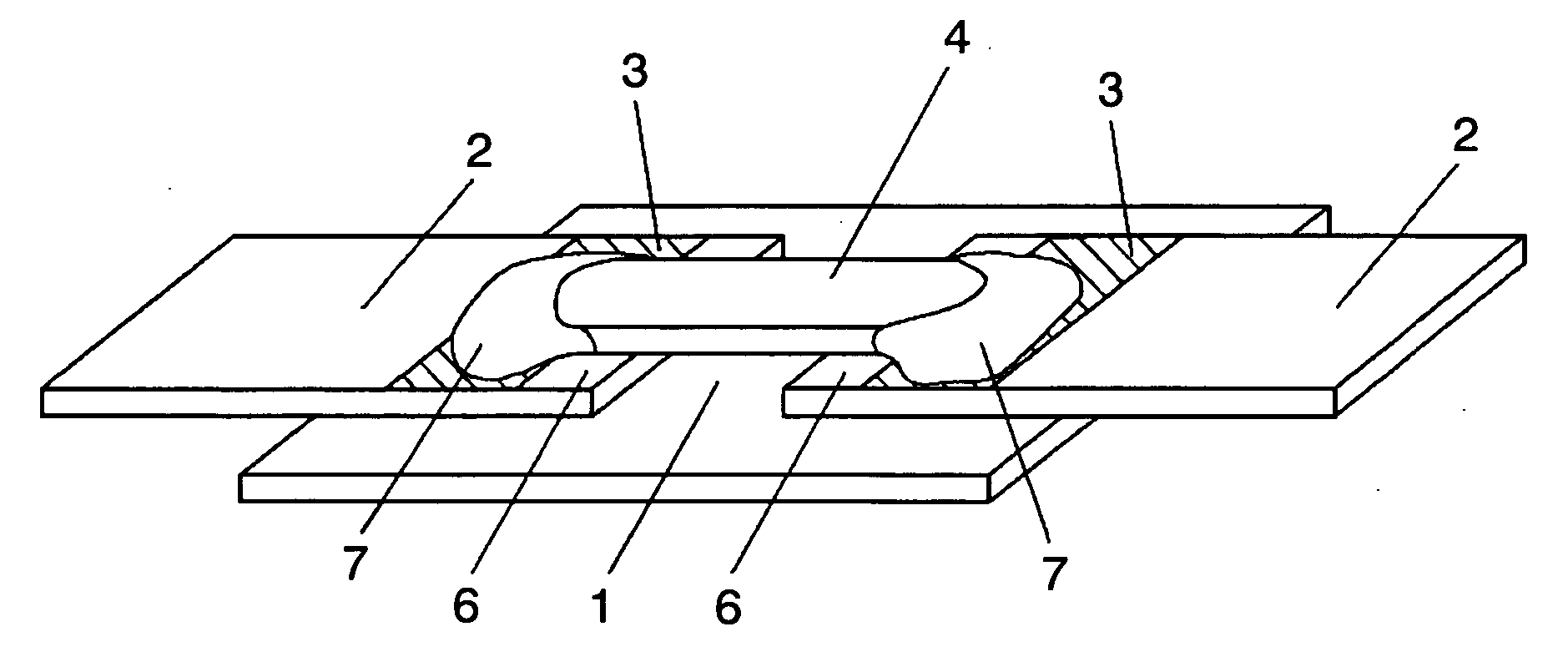
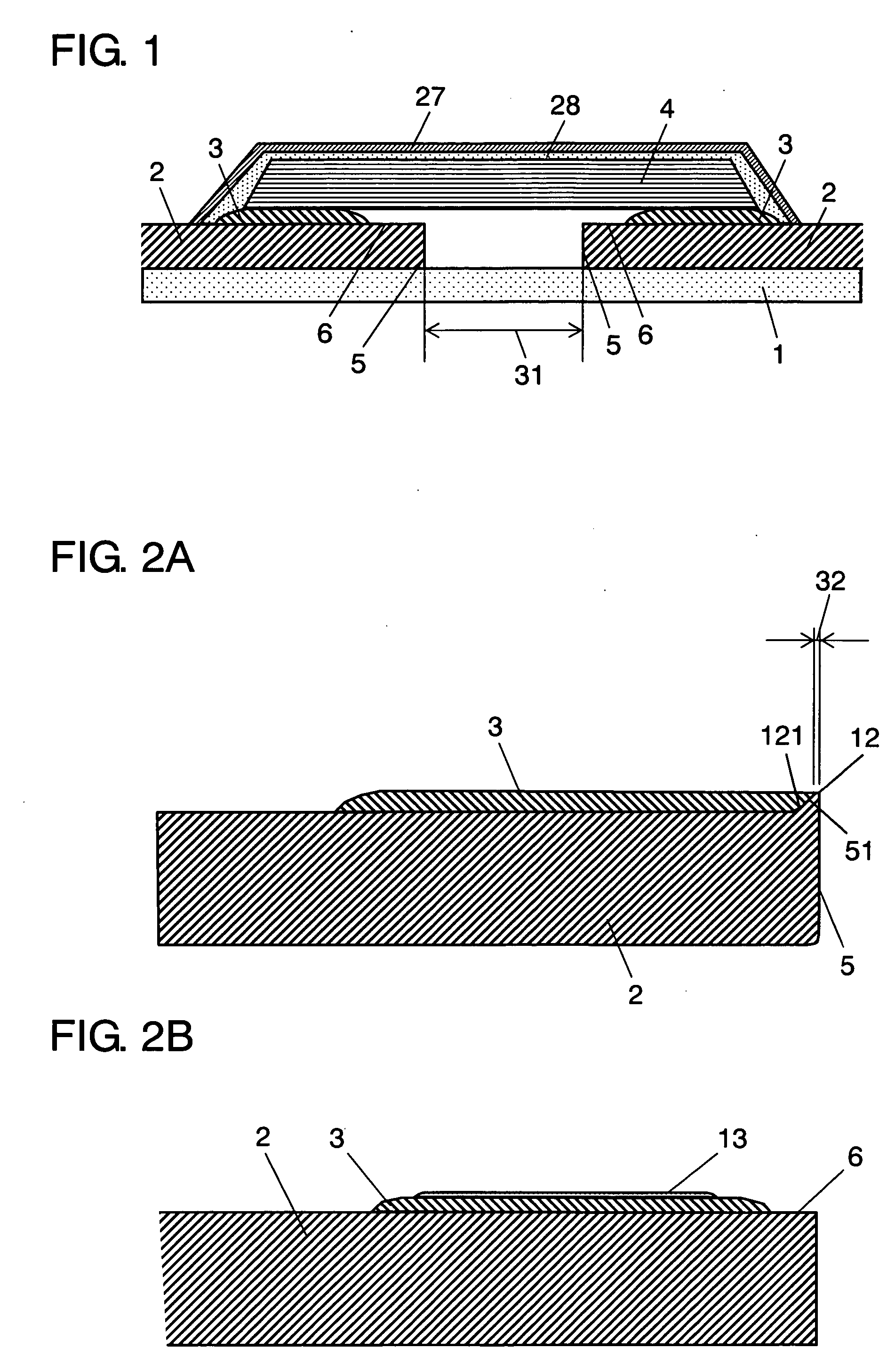
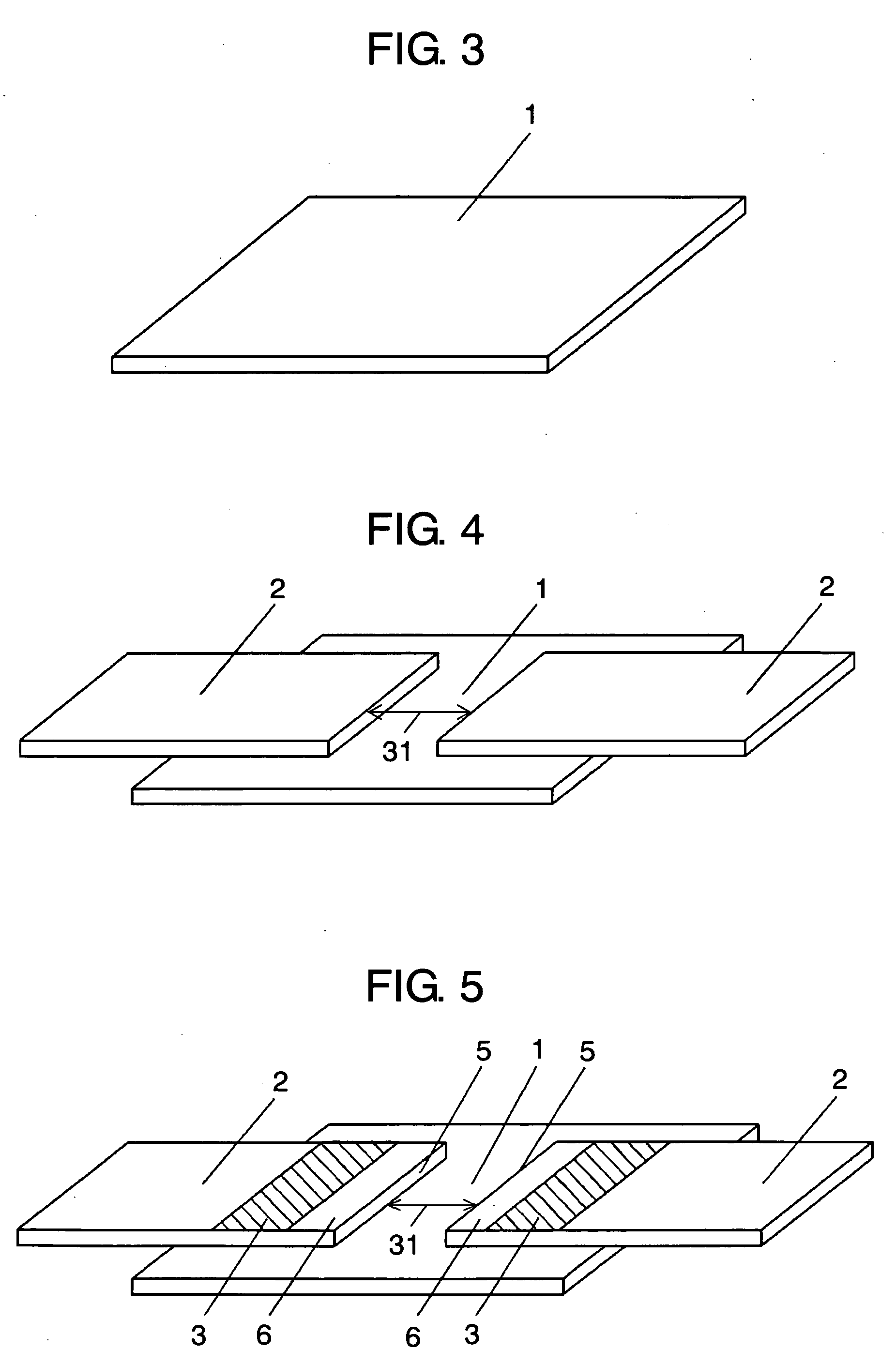
[0019]FIG. 1 is a lateral sectional view of a fuse in the first exemplary embodiment of the present embodiment. FIG. 2A and FIG. 2B are lateral sectional views of lead terminals. FIG. 3 to FIG. 7 are drawings showing steps in manufacturing the fuse and FIG. 8A to FIG. 8C are drawings showing steps in welding the fuse element. FIG. 9 is a perspective view of a fuse melted down.

[0020] Substrate 1 is made of an insulating material, such as a plastic, glass, or ceramic material, or it may be made of metal with an insulating coating formed thereon. In the present embodiment, an alumina ceramic plate is used as su...


PUM


Abstract

A fuse has a pair of lead terminals disposed on a substrate, an intermediate layers for welding formed on the surface of at least one of the lead terminals, and a fuse element. The fuse element is welded to the pair of lead terminals through the intermediate layer so as to span the same. Further, the intermediate layer is formed on at least one of the lead terminals except a face thereof opposing each other. Owing to this configuration, after the fuse has melted down, the melted fuse element is prevented from being spread out into the space between the opposing faces of the lead terminals and insulation therebetween is secured.

Description

TECHNICAL FIELD [0001] The present invention relates to a fuse used for preventing failure of electronic equipment and the like due to abnormal heating and overcurrent, a battery pack using the fuse, and a method of manufacturing the fuse. BACKGROUND ART [0002] In order to prevent occurrence of a failure of electronic equipment due to abnormal heating of a pack battery used in electronic equipment such as mobile telephones, it is required that a temperature fuse be mounted on the pack battery. It is also required that a current fuse be mounted on electronic equipment to prevent occurrence of a failure due to abnormal current. [0003] In a conventional temperature fuse, a fuse element which melts down when it reaches a predetermined temperature is provided at its both ends with terminal portions and the terminal portions are connected to a circuit such as a power supplying circuit. When abnormal heating is produced in a component constituting a power supply or the like (such as a batt...

Claims


Application Information

Patent Timeline
IPC IPC(8): H01H37/76H01H69/02H01H85/02H01H85/045H01H85/143H01H85/18H01M50/583
CPCH01H37/761H01H85/143H01M2/348H01M2/34H01H2085/025Y02E60/10H01M50/581H01M50/583H01H85/02H01H85/00
Inventor MUKAI, TAKAHIROIZAKI, MASATOSHISAKAMOTO, YOSHIOSENDA, KENJI
Owner PANASONIC CORP
Learn More