Catheter system having a balloon angioplasty device disposed over a work element lumen

a catheter system and angioplasty technology, applied in the field of catheter systems, can solve the problems of stenosis, narrowing of the vascular channel, restricted blood flow, and serious health risks of peopl

Inactive Publication Date: 2004-12-30
BOSTON SCI SCIMED INC
View PDF27 Cites 3 Cited by
  • Summary
  • Abstract
  • Description
  • Claims
  • Application Information

AI Technical Summary

Benefits of technology

[0012] The catheter of the present invention will allow for the performance of rapid and convenient balloon angioplasty and imaging or other treatment of the diseased vessel while minimizing the need to reposition the catheter body between procedures. Additionally, the distal end of the catheter fill be relatively narrow to allow for movement of the catheter into restricted spaces of the patient's vascular system and particularly into narrow regions and stenoses within the coronary arteries.

Problems solved by technology

Localized accumulation of deposits within regions of the blood vessels may result in stenosis, or narrowing of the vascular channel.
When this occurs, blood flow is restricted and the person's health is at serious risk.
Exchanging the imaging catheter for an interventional or other catheter within a patient's vascular system is time consuming and may be injurious to the patient.
The blood vessel interior is delicate, may be weakened by disease, and is therefore susceptible to injury from movement of the catheter body within it.

Method used


Image

  • Catheter system having a balloon angioplasty device disposed over a work element lumen
  • Catheter system having a balloon angioplasty device disposed over a work element lumen
  • Catheter system having a balloon angioplasty device disposed over a work element lumen

Examples


Embodiment Construction

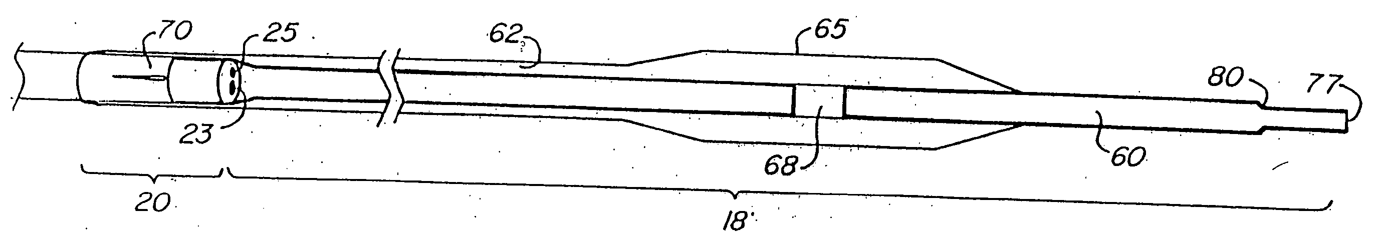
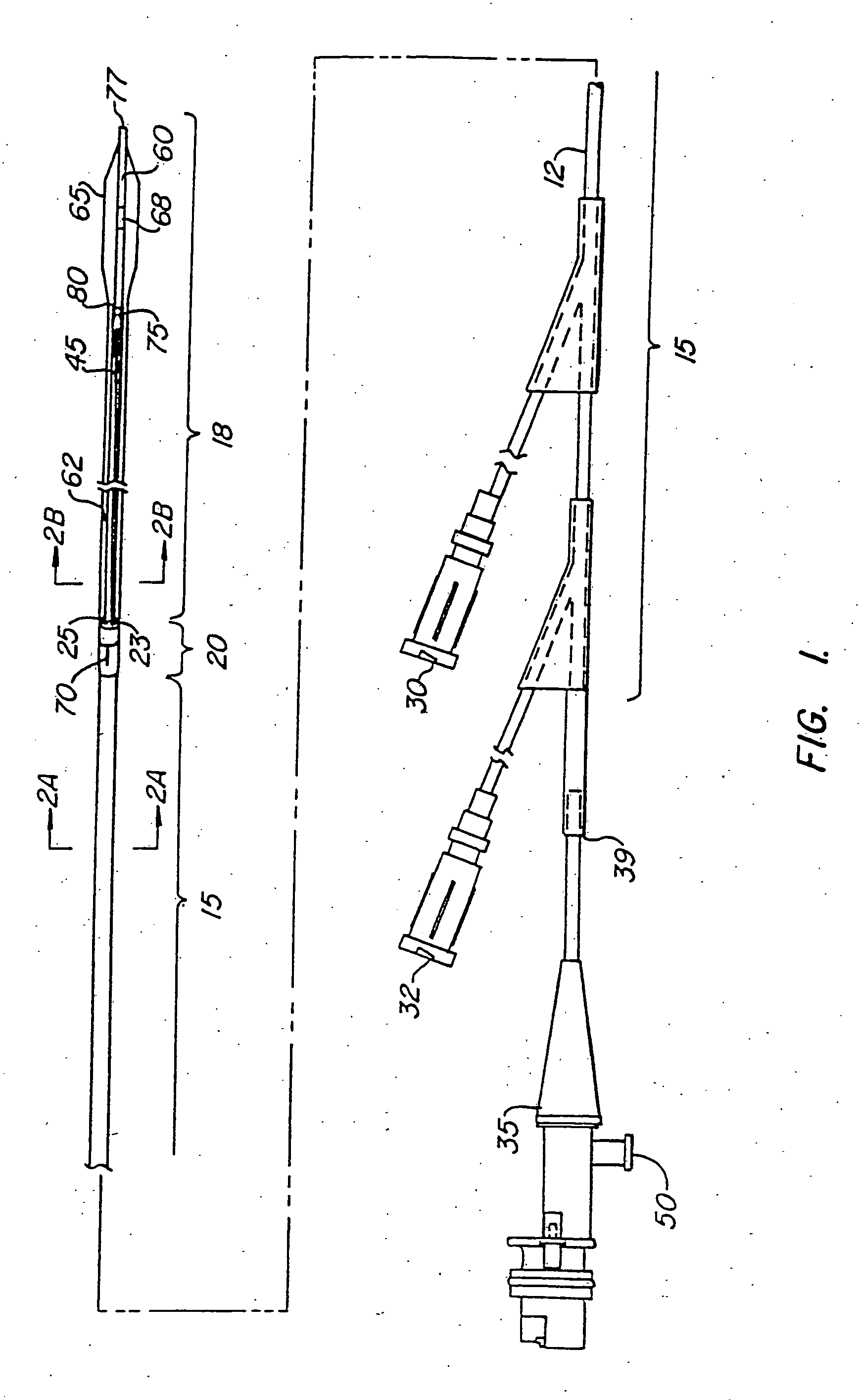
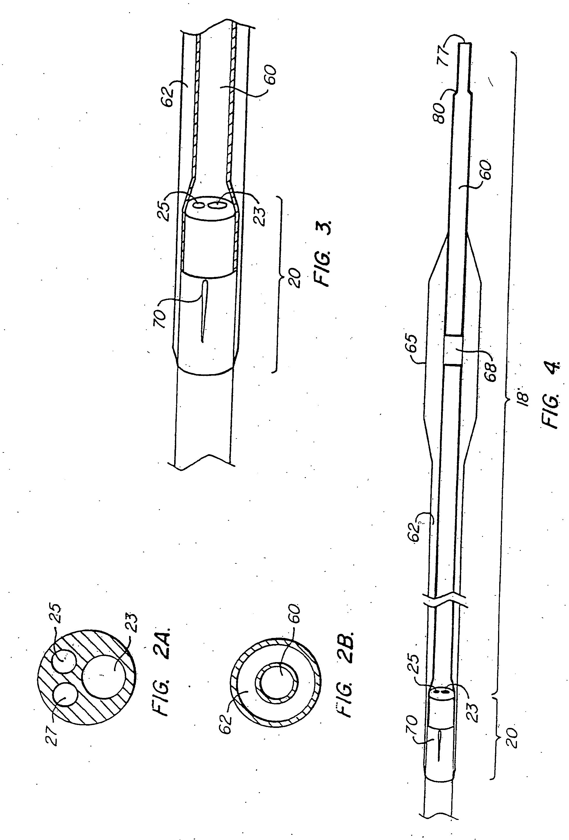
[0018] A catheter according to the present invention will comprise an elongate catheter body having proximal and distal ends and at least two regions, a proximal region and a distal region. The proximal region of the catheter body will have at least two lumens extending at least partly therethrough. The distal region of the catheter body will have a single common lumen in communication with both of the lumens of the proximal region. Additionally, an inflatable angioplasty balloon will be disposed about the common lumen of the distal region of the catheter.

[0019] In use, a catheter according to the present invention will be advanced over a guidewire into a patient's vascular system. First, the guidewire will be advanced alone into the patient until the guidewire lies within a particular region of interest. This will typically be a region in which a blood vessel has been narrowed by a stenotic lesion. The distal end of the guidewire will be advanced into the region of stenosis with th...


PUM


Abstract

An intravascular catheter system has a balloon angioplasty device disposed about a common lumen near its distal end. The common lumen is in communication with multiple lumens within a proximal region of the catheter body to allow for positioning of the catheter over a movable guide wire and convenient delivery of imaging or interventional devices to a desired region of the blood vessel being treated.

Description

[0001] The present application is a continuation of co-pending U.S. patent application Ser. No. 09 / 379,930, filed on Aug. 23, 1999, which is a continuation of U.S. patent application Ser. No. 08 / 861,397, filed on May 21, 1997, now U.S. Pat. No. 5,941,870, which is a continuation of U.S. application Ser. No. 08 / 504,363, filed on Jul. 19, 1995, now abandoned, which is a continuation of U.S. application Ser. No. 08 / 291,215, filed on August 16, 1994, now abandoned, which is a continuation of U.S. application Ser. No. 08 / 100,642, filed on Jul. 30, 1993, now U.S. Pat. No. 5,364,347, which is a continuation of U.S. application Ser. No. 07 / 975,752, filed on Nov. 13, 1992, now abandoned. The priority of these prior applications is expressly claimed and their disclosures are hereby incorporated by reference in their entirety.[0002] 1. Field of the Invention[0003] The present invention relates generally to catheter systems for imaging and treatment of stenoses within a patient's vascular syste...

Claims


Application Information

Patent Timeline
Patent Type & Authority Applications(United States)
IPC IPC(8): A61B8/12A61M25/00A61M29/02
CPCA61B8/12A61B8/4461A61M25/0029A61M25/104A61M2025/0004A61M2025/0039A61M2025/004A61M2025/1079
Inventor JANG, YUE-TEH
Owner BOSTON SCI SCIMED INC
Why Eureka
Try Eureka