
Panel formwork system

a formwork system and panel technology, applied in the direction of moulding surfaces, building components, mould fastening means, etc., can solve the problems of time-consuming, time-consuming, and the inability to adjust the relative position of the side forms when bolting to the platform

Inactive Publication Date: 2004-12-02
HC PRECAST SYST
View PDF18 Cites 19 Cited by
  • Summary
  • Abstract
  • Description
  • Claims
  • Application Information

AI Technical Summary

Problems solved by technology

This is very time consuming, as it requires manual labour to bolt the side forms to the platform.
Furthermore, to remove the cast panel from the formwork system, it is normally necessary to unbolt the bracing from the platform, which is again time consuming.
This arrangement of bolting the side forms to the platform does not facilitate adjusting the relative positions of the side forms to adjust the width and length dimensions of the panel to be cast.
Whilst these moulds allow flexibility in width, the holding method of side moulds are usually not firm and this leads to bulging at the edge of wall panel and escape of grout during casting of wall panels.

Method used


Image

  • Panel formwork system
  • Panel formwork system
  • Panel formwork system

Examples


Embodiment Construction

[0015] The invention will be hereinafter described with reference to the accompanying drawings which illustrate two preferred embodiments of the invention. The drawings however are merely illustrative of how the invention might be put into effect, so that the specific form and arrangement of the features shown is not to be understood as limiting on the invention.

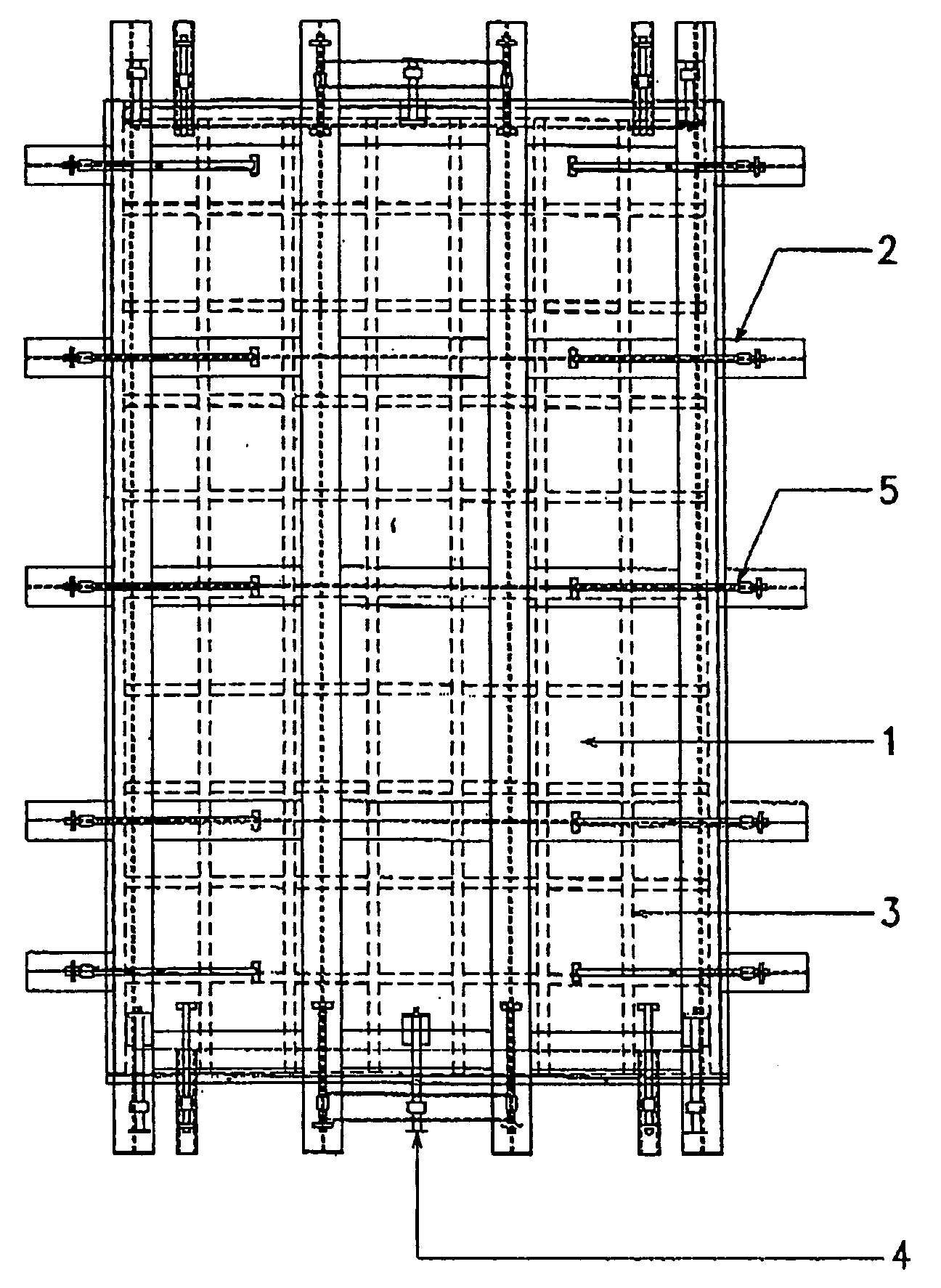
[0016] FIG. 1.0 is a plan view showing the formwork system for casting prefabricated wall panels with retractable bracing according to the invention.

[0017] FIG. 2.0 is a side view of a linear retractable bracing system according to one preferred embodiment of the invention.

[0018] FIG. 3.0 is a side view of a lever retractable bracing system according to another preferred embodiment of the invention.

[0019] FIG. 4.0 is a plan view showing the formwork system for casting prefabricated wall panels with pattern and decorative features.

[0020] FIG. 5.0 is a cross section showing the formwork system for casting prefabricated wall-pa...


PUM


Abstract

Formwork system for the process of casting prefabricated wall and slab panels that is flexible in width and height is provided. This formwork system includes two types of retractable bracing structures that are located on the sides and ends of mould structure. The height and width of panels can be varied by moving the linear retractable bracing structure, while the lever retractable bracing structure holds the side form firmly by clamping down the side form to the platform of the support structure. The thickness of the panel to be cast can be varied by using different modules of side form that are designed to produce a series of modules of various heights. Various patterns on the wall can be designed by incorporating specially designed channels in the mould.

Description

[0001] This invention relates to formwork system for use in casting prefabricated panels. The formwork system is particularly suited for use with wall panels and it will be convenient to hereinafter describe the invention in relation to this particular application. It should be appreciated however that the invention is not limited to prefabricated wall panels but rather is intended to include other panels such as floor slab panels.BACKGROUND TO THE INVENTION[0002] Conventional formwork system used in casting prefabricated wall panels are generally made up of cumbersome parts that must be assembled to define the sides oft he panel to be cast. The formwork system generally includes a platform defining a surface of the panel and a number of side forms defining the sides of the panel to be cast. The side forms are normally braced to the platform by bolting the side forms to the platform. This is very time consuming, as it requires manual labour to bolt the side forms to the platform. Fu...

Claims


Application Information

Patent Timeline
IPC IPC(8): B28B7/00B28B7/02
CPCB28B7/0017B28B7/0032B28B7/02
Inventor HUR, TEOW BENG
Owner HC PRECAST SYST
Learn More