
Digital instantaneous direction finding system

a digital instantaneous and direction finding technology, applied in direction finders, direction finders using radio waves, instruments, etc., can solve the problems of system deception, deprived of its direction finding capabilities, and limited frequency range for which the direction finding system can provide correct azimuth or elevation information

Inactive Publication Date: 2004-08-19
REGEV ZVI
View PDF1 Cites 30 Cited by
  • Summary
  • Abstract
  • Description
  • Claims
  • Application Information

AI Technical Summary

Problems solved by technology

The range of frequencies for which the direction finding system can provide a correct azimuth or elevation information is limited by a couple of conditions.
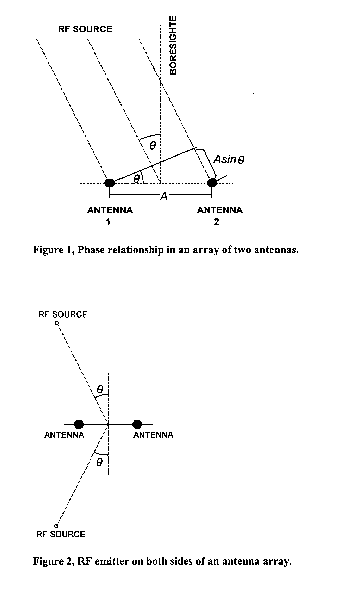
If this distance is greater than the wavelength of the incoming RF signal, the system is unable to determine the exact phase difference between the antennas.
A second limitation depends on the frequency of the clock.
The monpulse radar receiving the two signals of different phases is unable to determine the true direction from which these signals come, and thus is deceived and deprived of its direction finding capabilities.

Method used


Image

  • Digital instantaneous direction finding system
  • Digital instantaneous direction finding system
  • Digital instantaneous direction finding system

Examples


Embodiment Construction

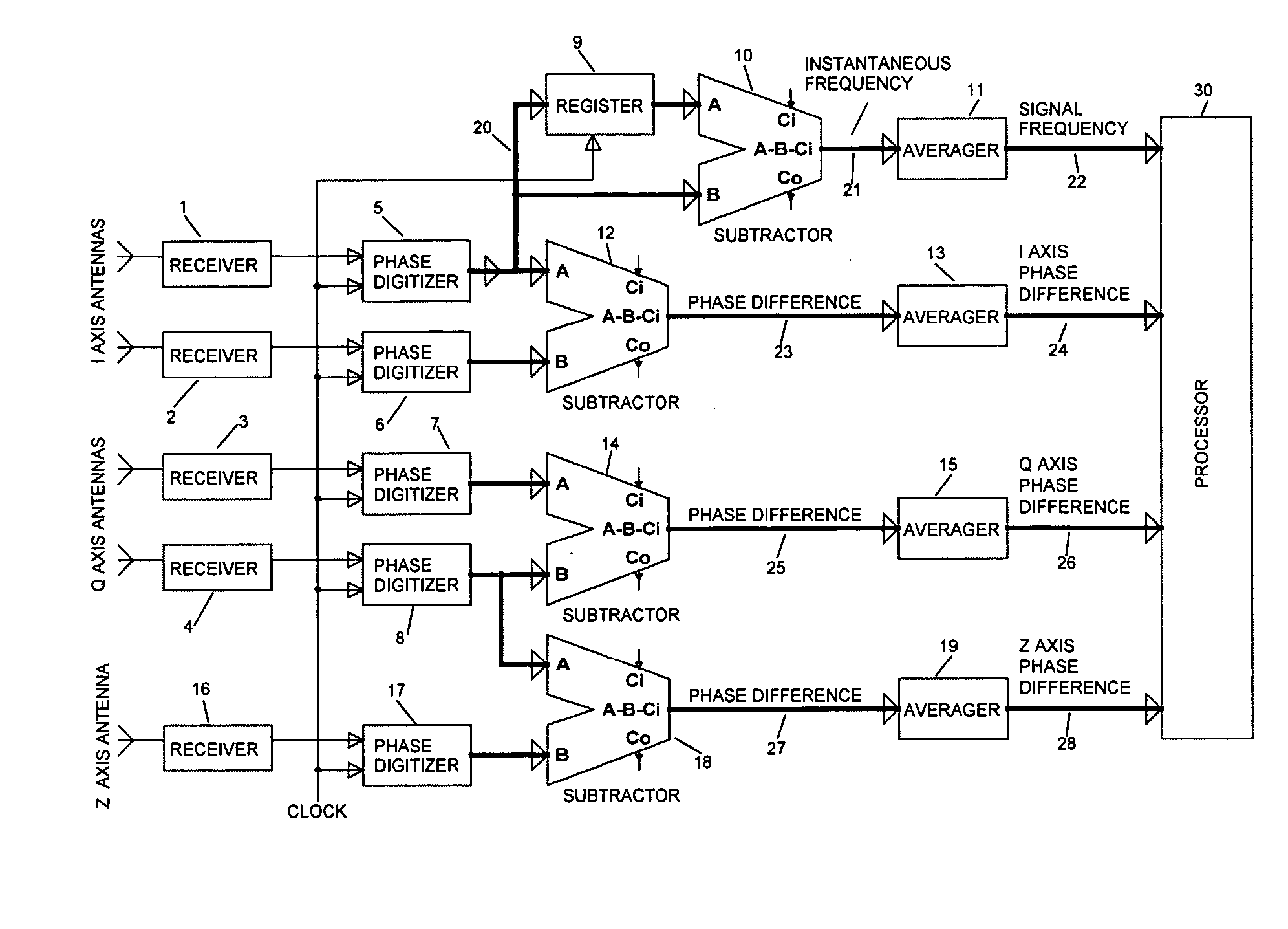
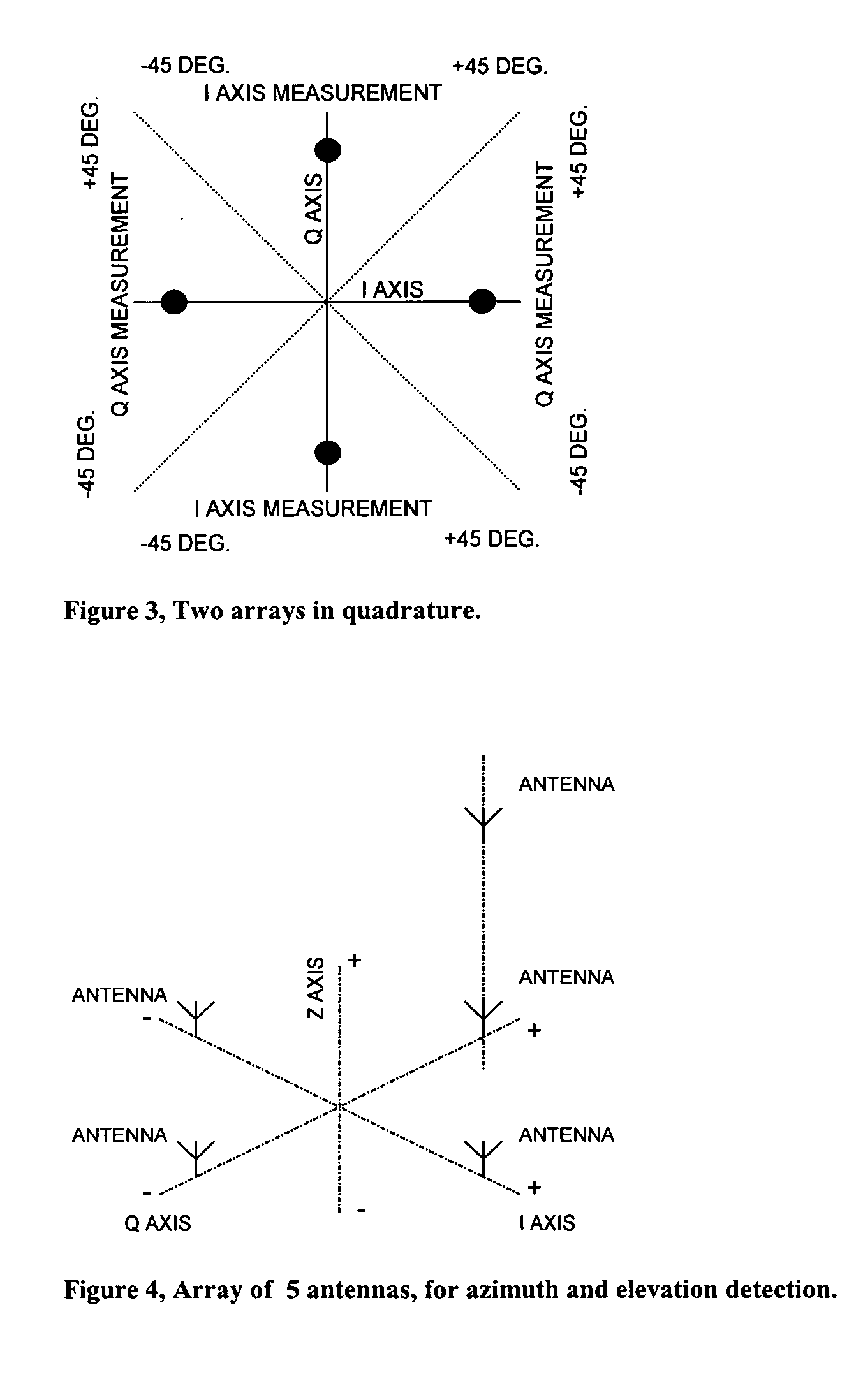
[0036] To better understand the description of this invention, refer to FIGS. 6, 7, and 8. FIG. 6 shows an embodiment of the system capable of determining the azimuth and elevation of an emitter of RF signal. As shown, 5 antennas are used, each connected to a radio frequency receiver. An embodiment of a typical RF receiver is shown in FIG. 7. The signal received by the antenna (100), is aplified by the amplifier (101), and then filtered by a bandpass filter (102). The bandpass filter guarantees that onlt signals at frequencies within the operational limits of the system are passed down to the system. The bandpass filter (102) is followed by another amplification stage (103). The output of the second amplification stage (103) connects to a power splitter (104) which splits the output of the amplifier (103) into two signals identical to the output of the amplifier (103) in all respects except for the power, which is divided, one half (111), and the other half (112), which are connecte...


PUM


Abstract

A system for finding the instantaneous spatial azimuth and elevation of a source of radio signals employing phase digitizers to measure the phase of arrival of a radio signal on an array of antennas. The phase digitizers providing digital indication of the phase of arrival, enable the determination of the azimuth, and elevetion of a source of radio signal, utilizing simple digital subtraction methods.

Description

[0001] This invention generally relates to passive direction finding antenna systems for radio waves, and in particularly to antenna arrays that continuously observe over 360 degree arc in space, to determine the spatial direction of an incoming wave, and produce a digital output code, representing the direction of the incoming wave.DESCRIPTION OF THE PRIOR ART[0002] Many prior art methods of detecting the spatial direction of incoming radio signals are used, utilizing rotating focused antenna beams, as well as circular antenna arrays and direction finding receivers. Burnham and Clark, describe a direction finding system wherein the system employs a circular antenna array energizing a phase shifting network that produces output signals whose time phase is directly proportional to a spatial angle of an incoming RF signal. Thus for each different spatial angle of an incoming RF signal the system produces a different time phase angle, which is sampled and digitized to produce a digital...

Claims


Application Information

Patent Timeline
Patent Type & Authority Applications(United States)
IPC IPC(8): G01S3/04G01S3/46
CPCG01S3/46G01S3/043
Inventor REGEV, ZVI
Owner REGEV ZVI
Learn More